Smart home cupboard

A smart home and cabinet technology, applied in the field of kitchen furniture, can solve the problems of food spoilage, contaminated food storage, lack of humidity detection and dehumidification devices, etc., to prevent gas poisoning and ensure safe storage.

Inactive Publication Date: 2018-04-17
大连函量科技发展有限公司
View PDF7 Cites 2 Cited by
  • Summary
  • Abstract
  • Description
  • Claims
  • Application Information

AI Technical Summary

Problems solved by technology

However, the existing cabinets do not have humidity detection and dehumidification devices. When storing food, it is easy to cause premature deterioration of food due to excessive humidity, and when storing food that is prone to odor, the whole cabinet is often affected by the taste of one food. For other stored food, it is inconvenient to find when there is too much food stored or the cabinet door is often opened, so that too much bacteria and dust enter the cabinet and contaminate the stored food

Method used


Image

  • Smart home cupboard
  • Smart home cupboard
  • Smart home cupboard

Examples


Embodiment 1

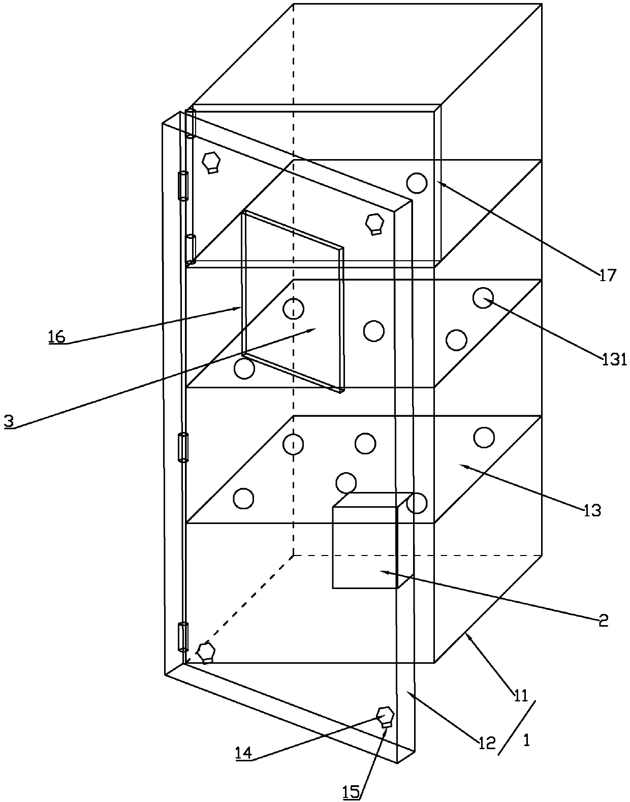
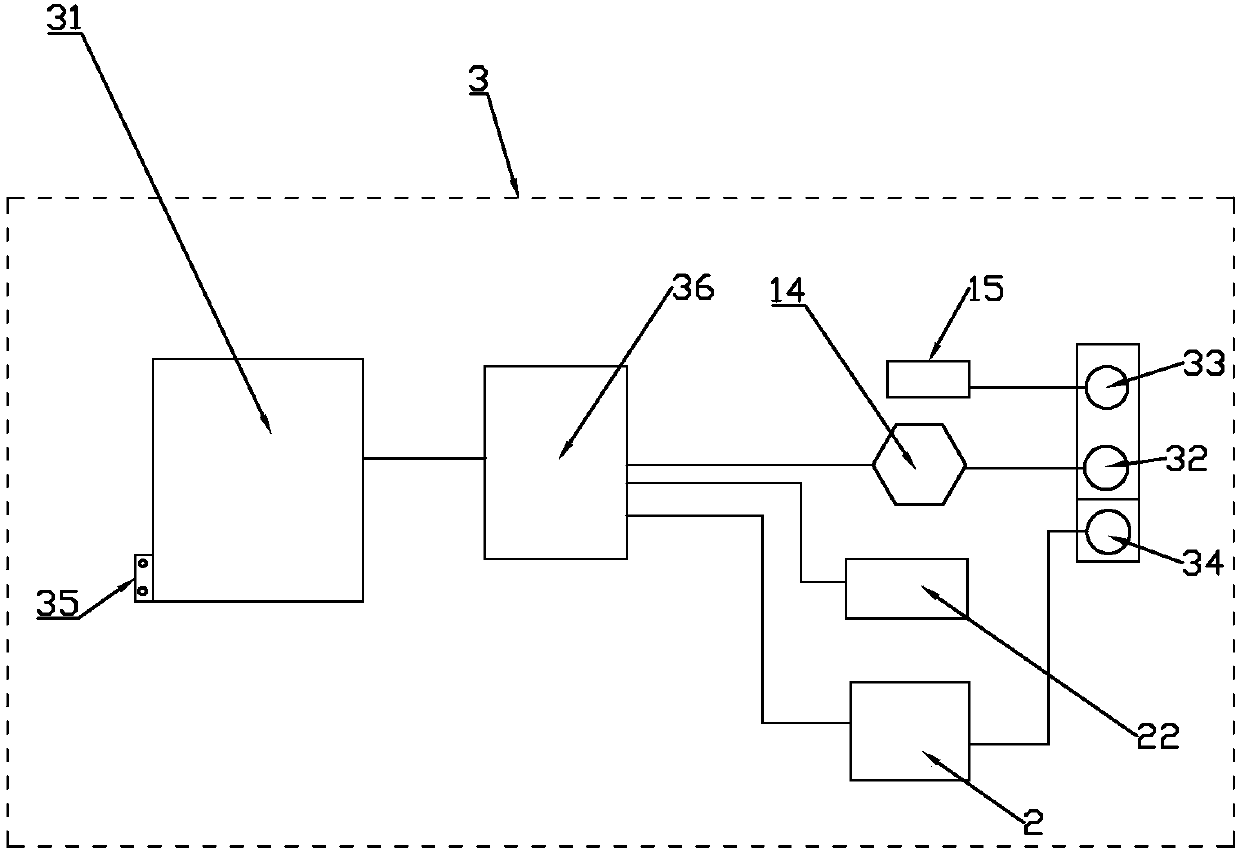
[0027] Such as Figure 1 to Figure 3 As shown, a smart home cabinet includes a cabinet body 1, a dehumidifier 2 and a display control assembly 3,

[0028] The cabinet body 1 includes a cabinet body 11 and a cabinet door 12 hingedly connected to one side of the open end of the cabinet body 11. A plurality of horizontal partitions 13 are arranged at equal intervals inside the cabinet body 11, and the inner sides of the four corners of the cabinet door 12 are A camera 14 and an illuminating lamp 15 are arranged respectively, and a square receiving groove 16 is arranged outside the cabinet door 12;

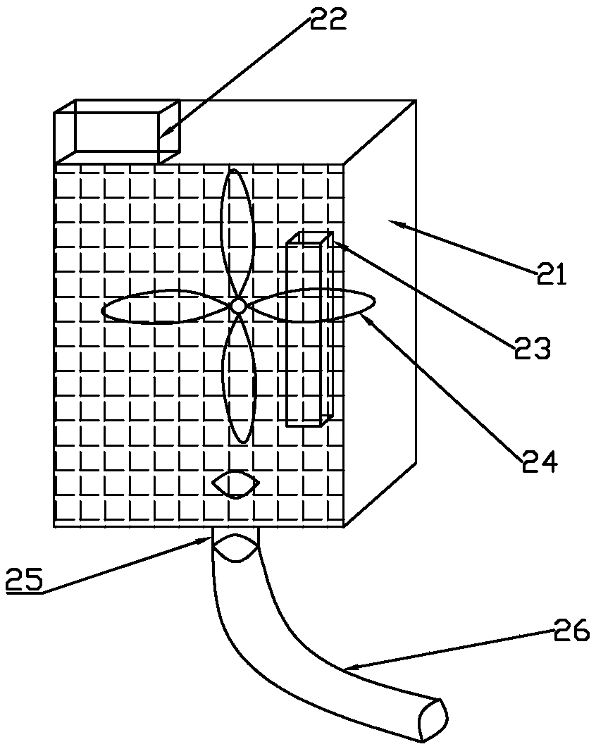
[0029] The dehumidification device 2 includes a housing 21, a humidity sensor 22, a semiconductor condenser main part 23 and a fan 24, and the rear of the housing 21 with a mesh structure in the front is fixed to the inside of the cabinet body 11 and the cabinet body 11 by screws. At the bottom of the opposite side of the door 12, the semiconductor condenser main part 23 is fixed ins...

Embodiment 2

[0045] Such as Figure 4 As shown, the difference between this embodiment and Embodiment 1 is that the outer surface of the cabinet body 11 is pasted with aluminum foil stickers 4 .

[0046] The aluminum foil sticker 4 effectively prevents external moisture from soaking the cabinet body 11, which is convenient for cleaning and prolongs the service life.

[0047] Further, in the above technical solution, the cabinet door 12 is provided with dust-proof rubber 5 around it.

[0048] The dust-proof rubber 5 is used to block tiny dust or smoke from entering the smart home cabinet, so as to prevent dust and dust.

[0049] Further, in the above technical solution, a gas detection alarm 6 is fixedly installed on the upper end of the cabinet body 11 , and the gas detection alarm 6 is connected to the central processing unit 36 ​​.

[0050] Preferably, the gas detection alarm 6 is a TX3301 gas detection alarm, and the gas detection alarm 6 is used to monitor whether the indoor gas leak...


PUM


Abstract

The invention discloses a smart home cupboard. The cupboard comprises a cupboard body, a dehumidification device and a display control component. The cupboard body comprises a cabinet and cabinet doors which are hinged to the side, at the end with an opening, of the cabinet. A plurality of horizontal partition plates are arranged inside the cabinet at equal intervals. One camera and one lighting lamp are arranged at the inner side of each corner of the cabinet doors separately. The dehumidification device includes a case, a humidity sensor, a semiconductor condenser main part and a fan. The semiconductor condenser main part is fixed to the interior of the case. The fan faces a net structure in front of the case and is fixed to the internal portion of the case. The humidity sensor is fixedoutside the case. A water outlet is formed in the lower end of the case. The display control component includes a display screen, a camera switch button, a lighting lamp switch button, a dehumidification device switch button, a humidity setting button and a central processor. According to the smart home cupboard, the humidity in the cabinet is controlled and convenience is brought to storage and management.

Description

technical field [0001] The invention belongs to the field of kitchen furniture, and in particular relates to a smart home cabinet. Background technique [0002] Today's cabinets, wardrobes and other furniture products occupy a relatively important position in daily life, and are essential living utensils in human life. With the needs of social development and the acceleration of the pace of life, improving the use efficiency of cabinets and other furniture products to meet people's needs has become an inevitable trend of social development. However, the existing cabinets do not have humidity detection and dehumidification devices. When storing food, it is easy to cause premature deterioration of food due to excessive humidity, and when storing food that is prone to odor, the whole cabinet is often affected by the taste of one food. For other stored foods, it is inconvenient to find when there is too much food stored or the cabinet door is often opened, so that too many bact...

Claims


Application Information

Patent Timeline
Patent Type & Authority Applications(China)
IPC IPC(8): A47B77/00A47B97/00A47B96/00A47B96/20F24F3/147
CPCA47B77/00A47B96/00A47B96/20A47B97/00A47B2220/0091F24F3/147
Inventor 韩亮
Owner 大连函量科技发展有限公司
Why Eureka
Try Eureka