Forced seal ball valve

A technology of forced sealing and ball valve, applied in the direction of engine sealing, valve device, cock including cut-off device, etc., can solve the problems of wear of sealing ring and ball valve, leakage of ball valve, etc., to prolong the service life and improve the effect of sealing effect.

Active Publication Date: 2018-04-17
希佛隆阀门集团有限公司
View PDF10 Cites 5 Cited by
  • Summary
  • Abstract
  • Description
  • Claims
  • Application Information

AI Technical Summary

Problems solved by technology

[0005] The purpose of the present invention is to provide a forced sealing ball valve, which solves the problem of leakage of the ball valve due to wear between the sealing ring and the ball valve after long-term use

Method used


Image

  • Forced seal ball valve
  • Forced seal ball valve
  • Forced seal ball valve

Examples


Embodiment Construction

[0030] The embodiments of the present invention will be described in detail below with reference to the accompanying drawings, but the present invention can be implemented in many different ways defined and covered by the claims.

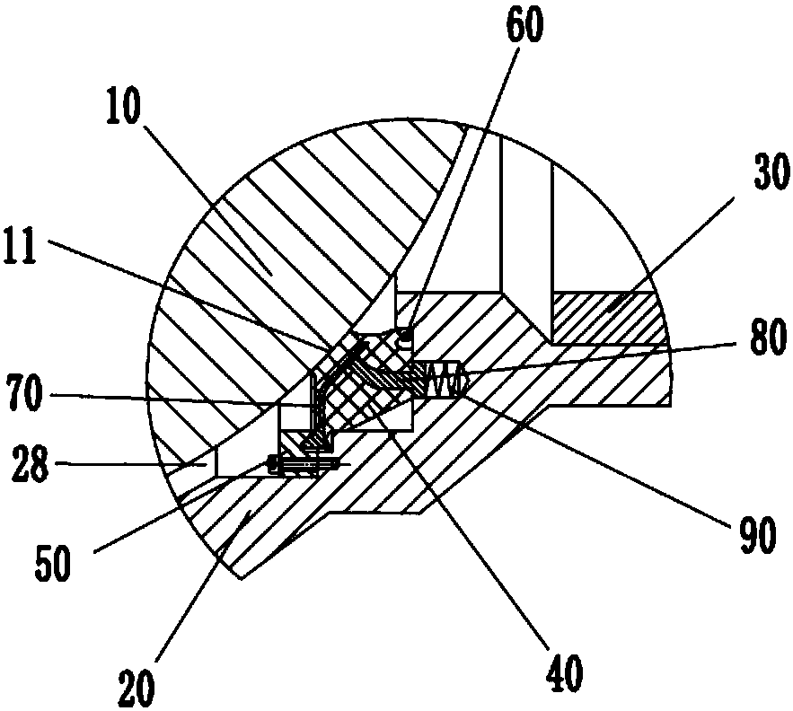
[0031] Refer below Figure 1 to Figure 7 The present invention is further described, as figure 1 The shown forced sealing ball valve includes a valve body 20 and a valve core ball 10, the valve core ball 10 is arranged in the valve cavity 28 of the valve body 20, and a sealing ring 40 is provided between the valve core ball 10 and the valve body 20, The right end of the valve body 20 is provided with a fourth hole 27, the second connecting pipe 30 is connected on the fourth hole 27, the valve body 20 is provided with a compression ring 50, the compression ring 50 is located in the valve cavity 28, the compression ring 50 Installed on the valve body 20 by screws, specifically, the screw passes through the screw hole 51 of the compression ring 50 and...


PUM


Abstract

The invention provides a forced seal ball valve which comprises a valve body and a valve element ball. The valve element ball is arranged in a valve cavity of the valve body, a seal ring is arranged between the valve element ball and the valve body, the valve body is provided with a pressing ring, the pressing ring is located in the valve cavity, and one end of the pressing ring abuts against oneend of the seal ring. According to the forced seal ball valve, the specially-shaped seal ring is adopted, the seal effect of the seal ring can be enhanced through the arrangement of multiple lips, aninclined plate of a first framework tightly presses the first lip portion under the effect of the pressing ring, the seal effect of the seal ring is improved, meanwhile, the gap brought by abrasion between the seal ring and the valve element ball can be compensated for, the elastic force of a spiral spring acts on a second framework and the first framework in sequence, the inclined plate tightly presses the first lip portion, the seal effect is improved, meanwhile, the gap brought by abrasion between the seal ring and the valve element ball can be compensated for, the sealing performance between the seal ring and the valve element ball is maintained, and therefore the service life of the ball valve is prolonged.

Description

technical field [0001] The invention relates to the field of valves, in particular to a forced sealing ball valve. Background technique [0002] The opening and closing part (ball) of the ball valve is driven by the valve stem, and the valve that rotates around the axis of the ball valve should generally be installed horizontally in the pipeline. [0003] Chinese patent 201610040710.6 discloses a ball valve. In order to ensure the sealing effect of the ball valve, a second sealing groove is opened in the valve body, and the second sealing ring installed in the second sealing groove is in contact with the surface of the valve core ball. , there is a third sealing groove in the valve seat, the third sealing ring installed in the third sealing groove is in contact with the surface of the valve core ball, through the cooperation between the second sealing ring, the third sealing ring and the valve core ball , thus ensuring the sealing effect of the ball valve. However, after a...

Claims


Application Information

Patent Timeline
Patent Type & Authority Applications(China)
IPC IPC(8): F16K5/06F16K5/20F16J15/3208F16J15/3232F16J15/3256
CPCF16J15/3208F16J15/3232F16J15/3256F16K5/0668F16K5/0689F16K5/201
Inventor 陈海燕
Owner 希佛隆阀门集团有限公司
Why Eureka
Try Eureka