
Flowerpot capable of automatically watering and working method therefor
A technology for automatic watering and flower pots, applied in automatic watering devices, botanical equipment and methods, non-electric variable control, etc., can solve the problems of flower withering, flower root rot, forgetting to water flowers, etc.
- Summary
- Abstract
- Description
- Claims
- Application Information
AI Technical Summary
Problems solved by technology
Method used
Image

Examples
Embodiment
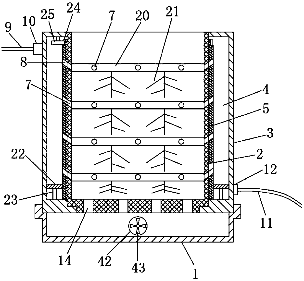
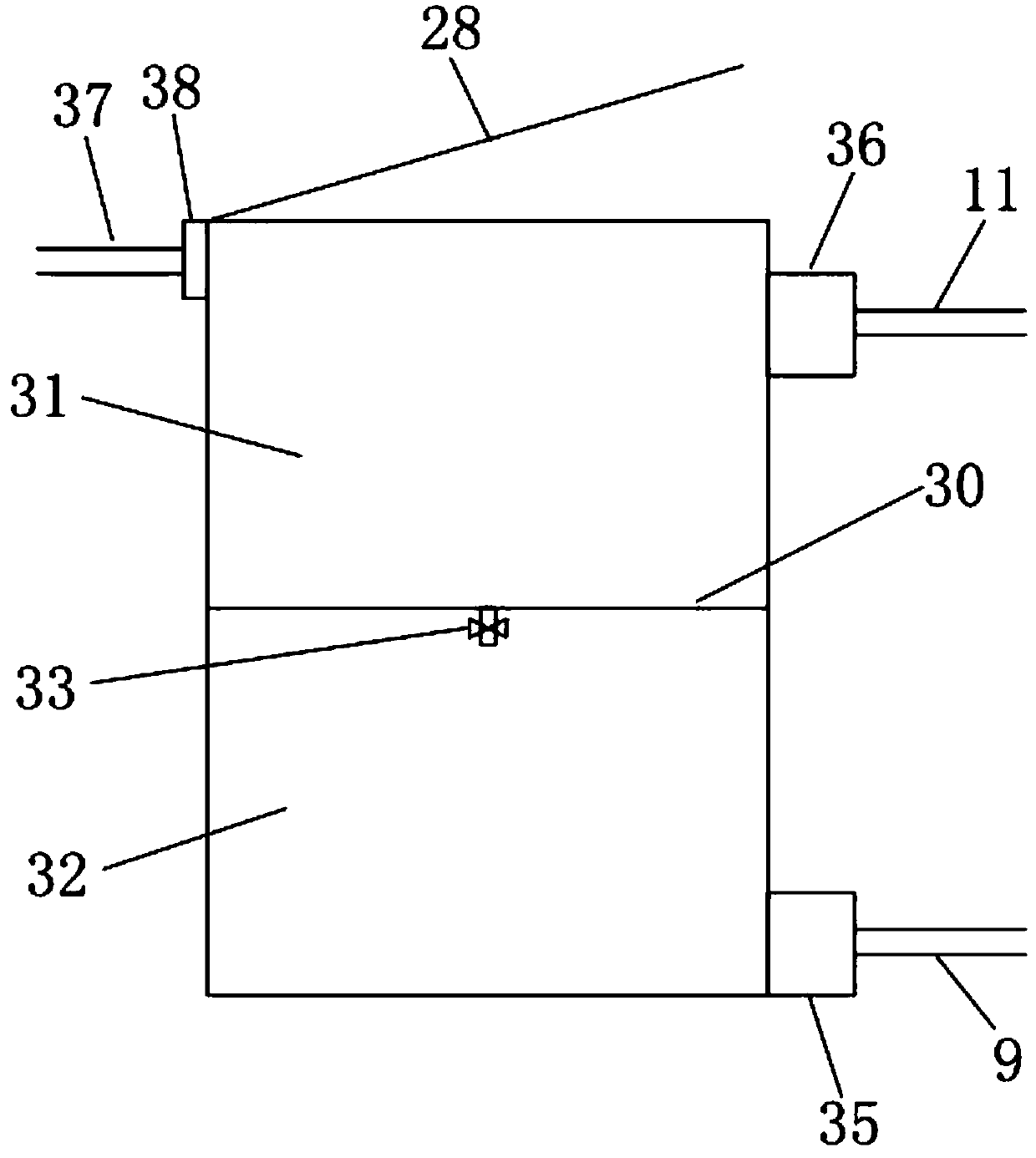
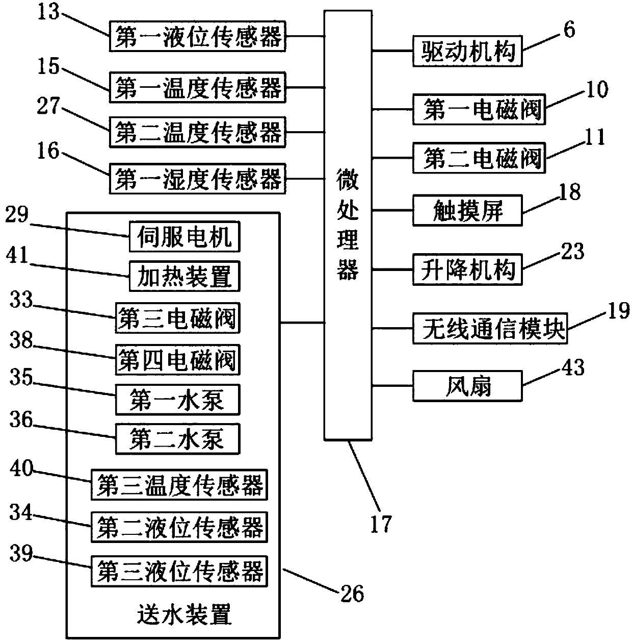
[0044] Embodiment: a kind of flower pot that can water automatically of the present embodiment, as figure 1 , figure 2 , image 3 , Figure 4 As shown, it includes a water delivery device 26, a flower pot seat 1 and a flower pot main body arranged on the flower pot seat 1. The flower pot main body includes an integrally formed inner pot 2 and an outer pot 3, and the inner pot 2 is a cylindrical body. A cylindrical hollow interlayer 4 is formed between the basin 2 and the outer basin 3, and the hollow interlayer 4 is provided with a sleeve 5 sleeved on the outside of the inner basin 2 and a drive mechanism 6 that can drive the sleeve 5 to rotate. There is also an annular water retaining plate 22 that separates the hollow interlayer into an upper cavity and a lower cavity, and a lifting mechanism 23 that can drive the annular water retaining plate 22 up and down. Water inlet structure, the water inlet structure includes several water inlet holes 7 located at the same height ...
PUM
 Abstract
Description
Claims
Application Information