
a paint sprayer

The technology of a paint spraying machine and a spraying head is applied in the directions of spraying device, pretreatment surface, and device for coating liquid on the surface, etc. It can solve the problems of uneven spraying, rising production cost, complicated modification of spraying equipment structure, etc., and achieve uniform spraying. Appropriate and fast spray paint effect

Active Publication Date: 2020-05-12
揭西县小天使电子电器有限公司
View PDF7 Cites 0 Cited by
  • Summary
  • Abstract
  • Description
  • Claims
  • Application Information

AI Technical Summary

Problems solved by technology

[0002] Most of the existing paint spraying machines spray paint toward the product from a fixed direction. During this process, the side of the product close to the spray head tends to receive more paint body, resulting in uneven spraying of the front and back of the product, especially for items with a small area. When spraying paint, the spray head can only spray paint in one direction. If the spraying method is reversed, not only will more man-hours be wasted, but also the structure of the spraying equipment needs to be modified more complicatedly, resulting in an increase in production costs. Finally, the quality of the painting will also be affected due to the long interval between the processes

Method used


Image

  • a paint sprayer
  • a paint sprayer
  • a paint sprayer

Examples


Embodiment Construction

[0015] Preferred embodiments of the present invention will be described in detail below.

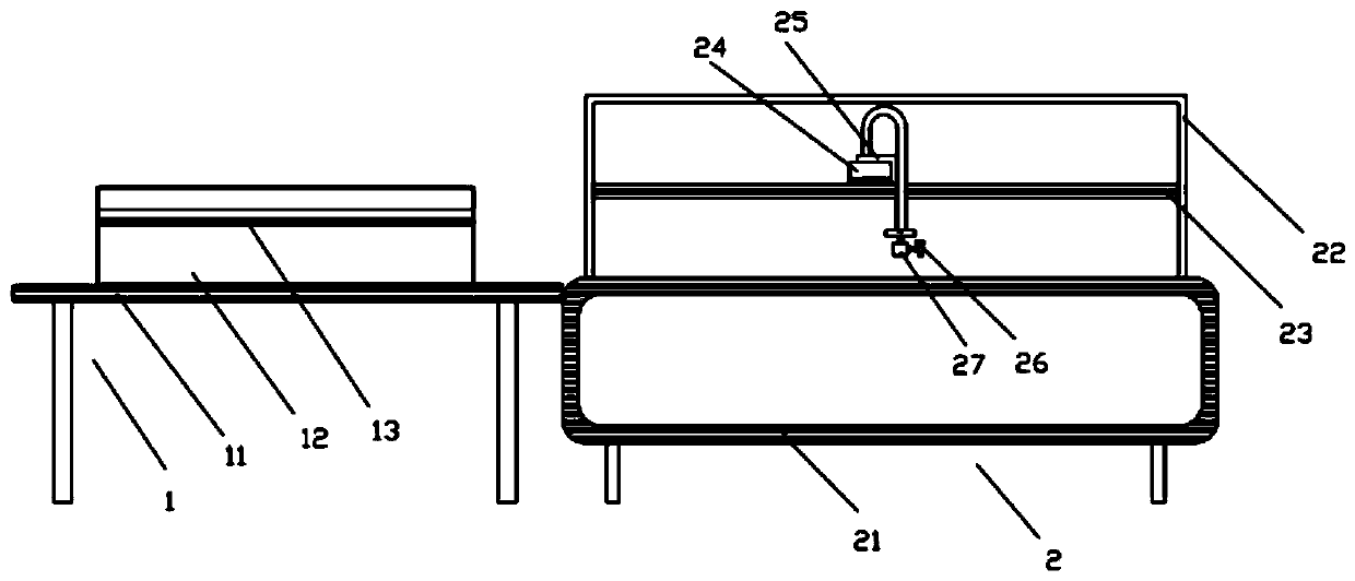
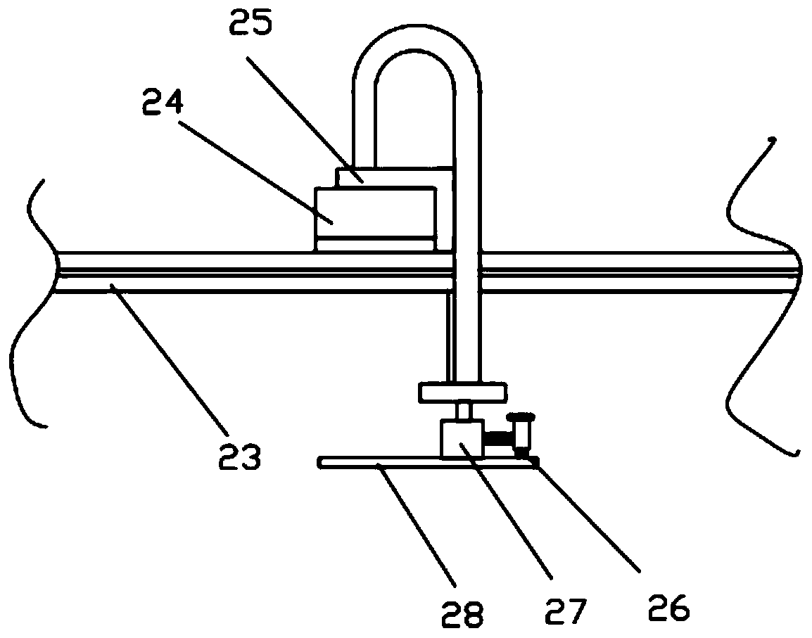
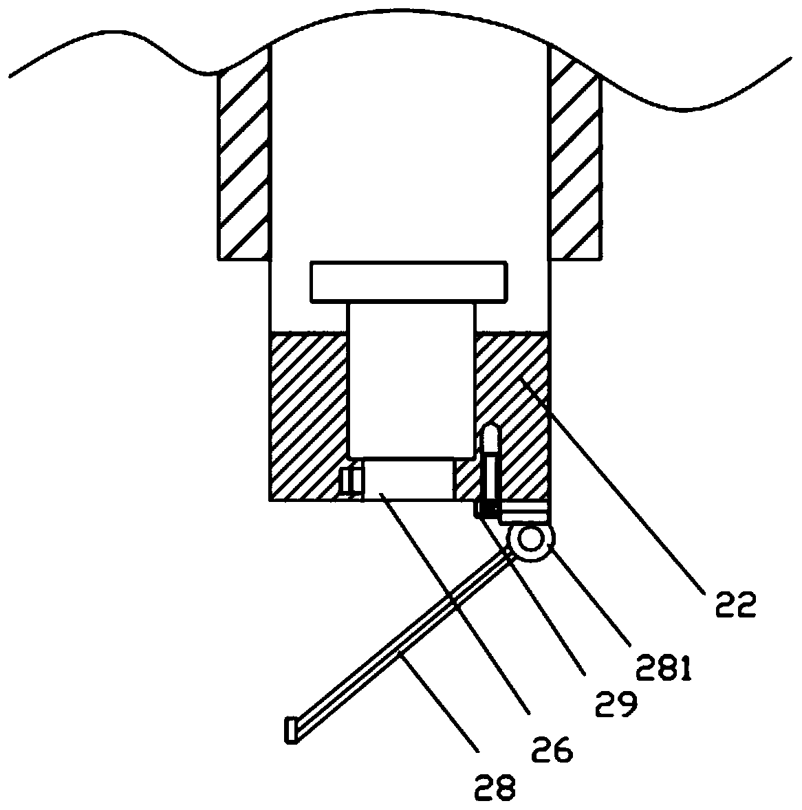
[0016] A paint spraying machine, comprising a drying workbench 1 and a paint spraying device 2, wherein a conveyor belt 21 is installed on the paint spraying device 2, and a paint spraying workbench 22 is arranged on the conveyor belt 21. Products are transferred on the conveyor belt 21, and the conveyor belt 21 stops rotating, and now the paint spraying head 26 moves forward and backward along the longitudinal rail 24 through the sliding plate 25, and the longitudinal rail 24 is located above the horizontal rail 23 and moves left and right along the horizontal rail 23, when the paint spraying head 26 adjusts its position, it starts The surface of the product is sprayed, and a spray angle control board 28 is arranged below the paint spray head 26. The paint spray angle control plate 28 is installed on the bottom of the connection module 27 through a rotating shaft 281, and one side of the...


PUM


Abstract

The invention belongs to the field of electronic organ processing devices and particularly relates to a paint sprayer. The paint sprayer comprises a drying working table and a paint spraying device. Aconveyor belt is mounted on the paint spraying device and provided with a paint spraying working table. The paint spraying working table is internally provided with a paint spraying head which movesin the front-rear direction along a longitudinal track through a sliding plate, and the longitudinal track is located above a transverse track and moves along the transverse track in the left-right direction. The paint spraying head moves forwards, backwards, leftwards and rightwards, and a paint spraying angle control plate is arranged below the paint spraying head. The paint spraying angle control plate is mounted at the bottom of a connecting module through a rotary shaft, and one side of the connecting module is fixedly connected with the paint spraying head. A paint spraying opening of the paint spraying head is downward. Even and suitable paint spraying can be ensured in the paint spraying process for products in different sizes, the situation that a paint body of the side close to the paint spraying head is too thick cannot occur, the paint spraying head does not need to be moved or turned by a large margin, the time and labor are saved, and the processing efficiency is not influenced.

Description

technical field [0001] The invention belongs to the field of electronic organ processing equipment, and in particular relates to a paint spraying machine. Background technique [0002] Most of the existing paint spraying machines spray paint toward the product from a fixed direction. During this process, the side of the product close to the spray head tends to receive more paint body, resulting in uneven spraying of the front and back of the product, especially for items with a small area. When spraying paint, the spray head can only spray paint in one direction. If the spraying method is reversed, not only will more man-hours be wasted, but also the structure of the spraying equipment needs to be modified more complicatedly, resulting in an increase in production costs. In the end, the quality of the painting will also be affected because the interval between processes is too long. Contents of the invention [0003] In view of the above defects of the prior art, the pres...

Claims


Application Information

Patent Timeline
Patent Type & Authority Patents(China)
IPC IPC(8): B05B13/04B05B15/62B05D3/06
CPCB05B13/04B05D3/067
Inventor 彭作捶彭启明
Owner 揭西县小天使电子电器有限公司
Learn More