
Turning plate structure of spray room

A technology of flipping and spraying booths, which is applied in the fields of removing smoke and dust, cleaning methods and utensils, chemical instruments and methods, etc., can solve the problems of inconvenient operation, time-consuming and laborious, reducing work efficiency, etc., to achieve easy and simple operation and improve color changing efficiency. Effect

Inactive Publication Date: 2018-04-20
ZHONGSHAN JUNHE ELECTRO MECHANICAL APP
View PDF4 Cites 0 Cited by
  • Summary
  • Abstract
  • Description
  • Claims
  • Application Information

AI Technical Summary

Problems solved by technology

[0002] At present, the function of the flip mechanism of the spray booth for powder spraying is single, and it can only be used for ventilation when the spray booth is spraying powder. When the color is changed and the spray booth needs to be cleaned, the staff needs to use the hand spray gun to clean the entire spray booth. Carrying out cleaning operations consumes a lot of labor costs and time, reducing work efficiency
In addition, the air regulating plate arranged on the flap is fixed by bolts. When the size of the ventilation opening needs to be adjusted, it is necessary to loosen the bolts to adjust the size of the ventilation opening and then tighten the bolts, resulting in inconvenient operation and time-consuming and laborious

Method used


Image

  • Turning plate structure of spray room
  • Turning plate structure of spray room

Examples


Embodiment Construction

[0016] The present invention will be further described in detail below in conjunction with the accompanying drawings and specific embodiments. However, it should be noted that the description of the following embodiments is schematic and does not constitute a specific limitation to the present invention.

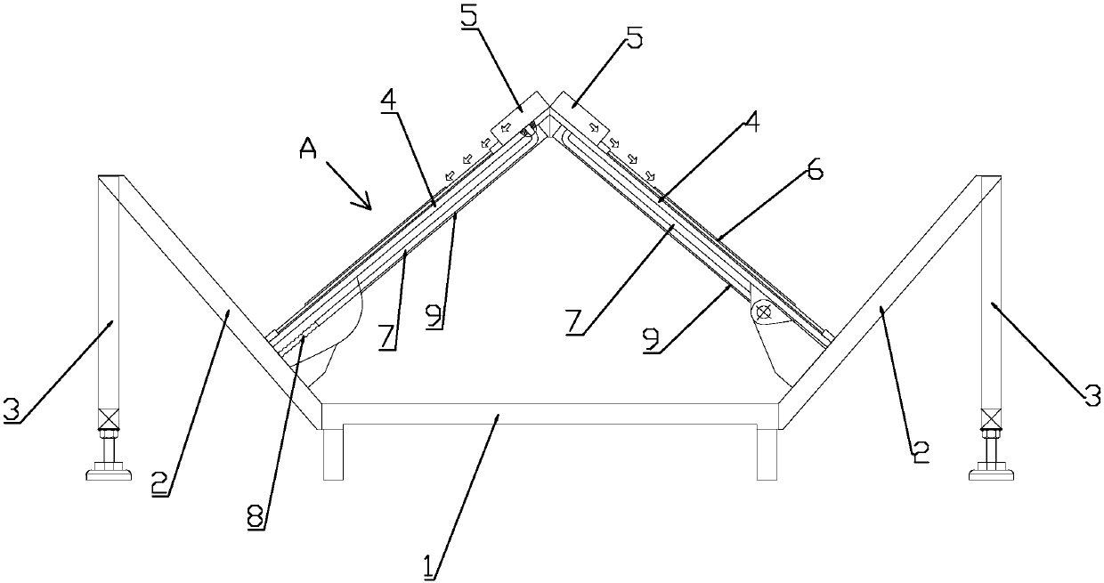
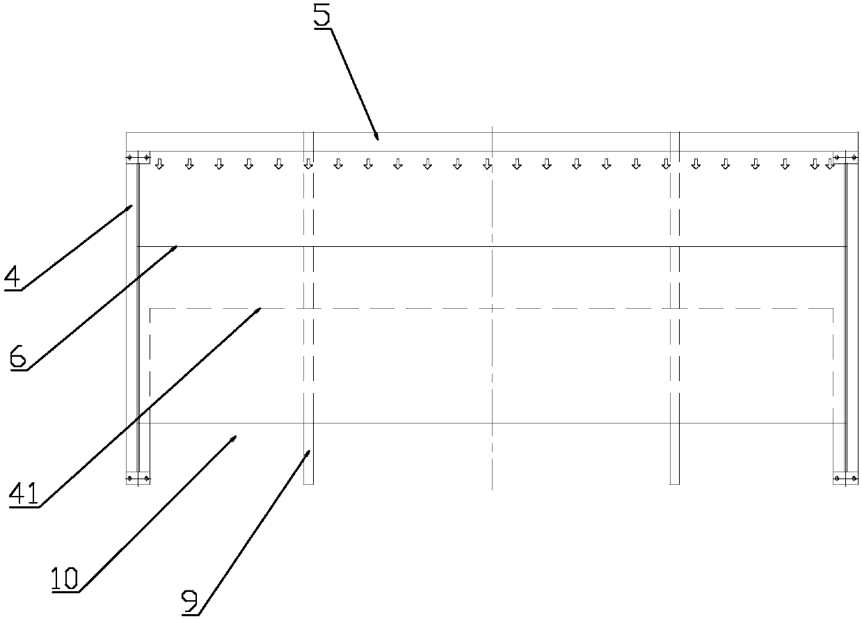
[0017] refer to figure 1 and figure 2 , a spray booth flap structure of the present invention, comprising: a base plate 1, two bottom side plates 2 connected to the two ends of the base plate 1 to form an outward opening, the bottom side plate 2 is provided with a Support the fixed support base 3, the inner side of the two bottom side panels 2 is hinged with a flap 4, and the other ends of the two flaps 4 abut against each other, the bottom panel 1, the two bottom side panels 2 and the two flaps 4 The air knife 5 is arranged at the end of the turning plate 4 away from the bottom side plate 2, and the air outlet direction of the air knife 5 is obliquely blowing downward to ...


PUM


Abstract

The invention discloses a turning plate structure of a spray room. The structure comprises a bottom plate and two bottom side plates which are respectively connected with two ends of the bottom plateand stretched outwards, wherein support seats for supporting and fixing are arranged on the bottom side plates; a turning plate is hinged inside each bottom side plate; the other ends of the two turning plates are butted against each other; a powder sucking space is formed by the bottom plate, the two bottom side plates and the two turning plates; air knifes are arranged on one ends, which are faraway from the bottom side plates, of the turning plates; and outlet air of the air knifes is obliquely downwards blown to outer surfaces of the turning knifes. The turning plate structure of the spray room, disclosed by the invention, has the beneficial effects that during powder spraying and color changing, the outer surfaces of the turning knifes are blown and cleaned through the air knifes onthe turning plates and staff only need to manually clean interiors of the turning plates, so that the color changing efficiency of the spray room is greatly increased; and further, gaps are arranged in one sides, which are close to the bottom side plates, of the turning plates, air adjusting plates are slidably arranged on the turning plates, air suction openings are formed between the gaps and the air adjusting plates and the size of the air suction openings can be easily adjusted according to the powder spraying amount and the specific process, so that the operation is easier and more convenient.

Description

technical field [0001] The invention relates to the field of powder spraying, in particular to a spray booth flap structure. Background technique [0002] At present, the function of the flip mechanism of the spray booth for powder spraying is single, and it can only be used for ventilation when the spray booth is spraying powder. When the color is changed and the spray booth needs to be cleaned, the staff needs to use the hand spray gun to clean the entire spray booth. Carrying out cleaning operations consumes a lot of labor costs and time, reducing work efficiency. In addition, the air regulating plate arranged on the flap is fixed by bolts. When the size of the draft opening needs to be adjusted, the bolts need to be loosened to adjust the size of the draft opening before tightening the bolts, resulting in inconvenient operation and time-consuming and laborious. Contents of the invention [0003] In order to overcome the shortcomings of the prior art, the invention pro...

Claims


Application Information

Patent Timeline
Patent Type & Authority Applications(China)
IPC IPC(8): B08B5/02B08B15/04
CPCB08B5/02B08B15/04
Inventor 罗森
Owner ZHONGSHAN JUNHE ELECTRO MECHANICAL APP
Learn More