
Damping hinge

A damping hinge and damping technology, applied in the field of damping hinges, can solve the problem of inability to adjust the damping force, and achieve the effect of adjustment

Active Publication Date: 2018-04-20
PINGHU FUDA HARDWARE MFG CO LTD
View PDF5 Cites 0 Cited by
  • Summary
  • Abstract
  • Description
  • Claims
  • Application Information

AI Technical Summary

Problems solved by technology

[0003] The purpose of the present invention is to provide a damping hinge, which can effectively solve the problem that the existing damping hinge cannot adjust the damping force

Method used


Image

  • Damping hinge
  • Damping hinge

Examples


Embodiment Construction

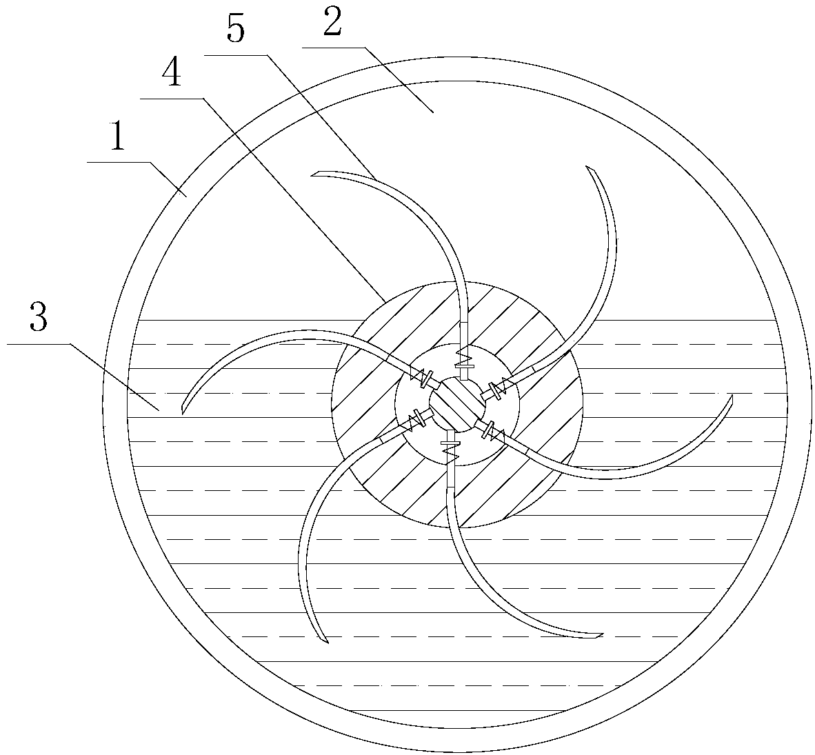
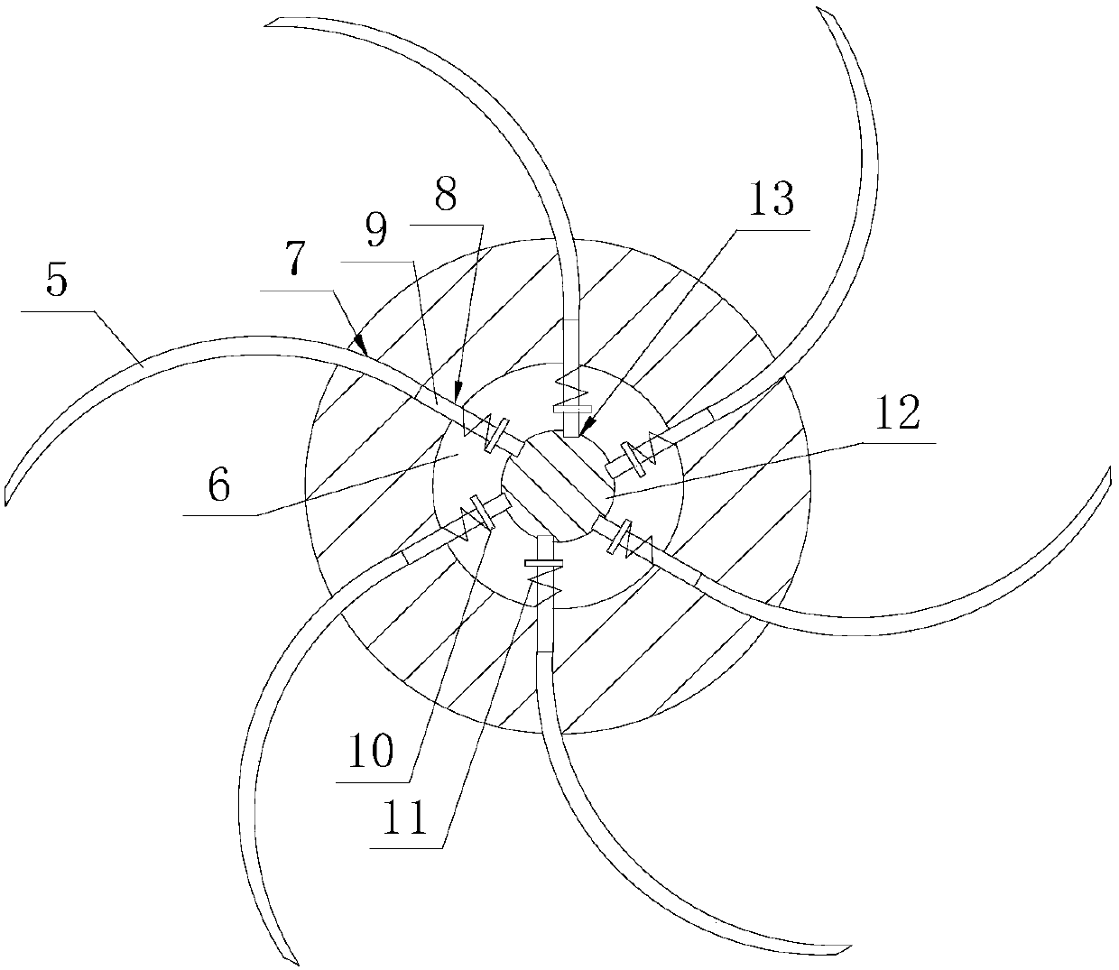
[0015] refer to figure 1 , figure 2 It is an embodiment of a damping hinge of the present invention, a damping hinge, comprising an outer cylinder 1, the two ends of the outer cylinder 1 are closed, a cavity 2 is provided in the outer cylinder 1, and a damping oil 3 is provided in the cavity 2, The volume of the damping oil 3 is smaller than the volume of the cavity 2, along the axis of the outer cylinder 1, a rotating shaft 4 passing through the outer cylinder 1 is provided, and the part of the rotating shaft 4 located in the cavity 2 is provided with a damping vane 5, the There are at least two damping blades 5, which are evenly distributed in the circumferential direction of the rotating shaft 4;

[0016] The rotating shaft 4 is provided with a control hole 6 along the axis, and the outer wall of the rotating shaft 4 is provided with a placement groove 7, the tail of the damping blade 5 is arranged in the placement groove 7, and the bottom of the placement groove 7 is pro...


PUM


Abstract

The invention discloses a damping hinge. The damping hinge comprises an outer cylinder; a rotating shaft is arranged in the outer cylinder; the rotating shaft is provided with damping blades, a control hole and a placing tank; the tails of the damping blades are arranged in the placing tank; a through hole is formed in the bottom of the placing tank; each damping blade is provided with a connecting rod penetrating through the through hole; the connecting rod and the through hole are slidingly arranged; an annular groove is formed in the part, extending into the control hole, of the front partof the connecting rod; a clamping ring sleeves the annular groove; the connecting rod is provided with a return spring between the clamping ring and the inner wall of the control hole; a control rod with a control groove is arranged in the control hole; the front end of the connecting rod is ejected in the control groove; and the depth of the control groove is gradually changed from deep to shallow. The damping hinge has the following advantages that the control rod is adjusted to enable the head of the connecting rod to slide in the control groove, so that the distances from the top ends of the blades to the rotating shaft are controlled, the contact areas of the damping blades and damping oil are adjusted, and adjustment of the damping force is realized; and through the return spring, recovery of the damping blades is realized.

Description

technical field [0001] The invention relates to a damping hinge. Background technique [0002] The damping hinge is a commonly used hardware used for the connection of two objects, such as doors and cabinets. It is generally composed of an outer cylinder and a rotating shaft. The outer cylinder is filled with damping oil. The oil interacts to achieve the damping effect, but the existing damping hinges often cannot adjust the damping force. Contents of the invention [0003] The purpose of the present invention is to provide a damping hinge, which can effectively solve the problem that the existing damping hinge cannot adjust the damping force. [0004] In order to solve the above technical problems, the present invention is achieved through the following technical solutions: a damping hinge, including an outer cylinder, the two ends of the outer cylinder are closed, a cavity is provided in the outer cylinder, and damping oil is provided in the cavity, so The volume of th...

Claims


Application Information

Patent Timeline
IPC IPC(8): E05F3/20E05F3/14
CPCE05F3/14E05F3/20
Inventor 徐国强
Owner PINGHU FUDA HARDWARE MFG CO LTD
Learn More