A Sparse Antenna for Forward-Looking Array SAR System

A sparse antenna and array technology, applied in radio wave measurement systems, radio wave reflection/reradiation, instruments, etc., can solve problems such as large amount of computation, low echo signal-to-noise ratio, limited array sparsity, etc., to achieve improved The effect of transmitting gain and improving the signal-to-noise ratio

Active Publication Date: 2021-07-30
中国人民解放军西安通信学院
View PDF7 Cites 0 Cited by
  • Summary
  • Abstract
  • Description
  • Claims
  • Application Information

AI Technical Summary

Problems solved by technology

At present, the forward-looking array SAR system faces the following problems in the design of the array antenna: due to the long array length and short signal wavelength, the traditional dense array antenna usually requires hundreds or thousands of array elements, resulting in high antenna cost and design complexity. Limits the Effective Realization of Forward-Looking Array SAR System
[0003] At present, there are mainly three methods that can effectively reduce the number of forward-looking array SAR array elements: one is the non-uniform sparse array method, the main literature is Lu Lan and Zhang Xiaoling published in "Computer Engineering and Application" in 2012 "based on The forward-looking 3D SAR model of optimized linear array by simulated annealing method”; this method reduces the number of array elements to a certain extent and avoids imaging grating lobes, but the non-uniform arrangement is not conducive to the rapid processing of cross-direction imaging, and the array’s very limited sparsity
The second is the multiple-input multiple-output (MIMO) technology. The main documents include Ma Chao, Gu Hong, etc. published in the "Journal of Radio Science" in 2015, "Airborne Forward-Looking Radar Imaging Algorithm with Multiple Input and Multiple Output Arrays" and WeiβM., Gilles M. published "Initial ARTINO RadarExperiments" on "EuropeanConference on Synthetic Aperture Radar" in 2010; they respectively proposed array antenna sparse distribution schemes based on time-division coherent MIMO, which effectively reduced the number of array elements, but due to the transmission and The aperture of the receiving array element is only slightly larger than half of the wavelength, and the transmitting and receiving gains are very limited, resulting in a small radar range or a low echo signal-to-noise ratio
The third is the array sparse sampling and compressed sensing method. The main literatures include "Research on 3D Imaging Method of Linear Array SAR Based on Compressive Sensing" published in "Acta Astronautics" by Wei Shunjun and Zhang Xiaoling in 2011, and Gao Lei and Zeng Yonghu et al. in 2014. "Design of array for airborne forward looking SAR based on compressed sensing" published in "IEEE International Conference on Signal Processing, Communications and Computing" in 2009; they not only effectively reduce the number of array elements, but also achieve cross-course super-resolution to a certain extent , but because they assume that the ground scattering source is sparse, but in reality most of the radar complex images are not very sparse, and the computational complexity is very large, which limits its further application
It can be seen that the above methods have some insurmountable problems in practical application, which limit their effective application.

Method used


Image

  • A Sparse Antenna for Forward-Looking Array SAR System
  • A Sparse Antenna for Forward-Looking Array SAR System
  • A Sparse Antenna for Forward-Looking Array SAR System

Examples


Embodiment Construction

[0024] In order to make the technical solutions and advantages of the present invention clearer, the present invention will be further described below in conjunction with specific embodiments and drawings in the forward-looking array SAR system.

[0025] The invention is mainly applied to the radar imaging of the real-aperture array antenna, and is currently mainly applicable to the short-distance imaging platform of the high-frequency band array radar.

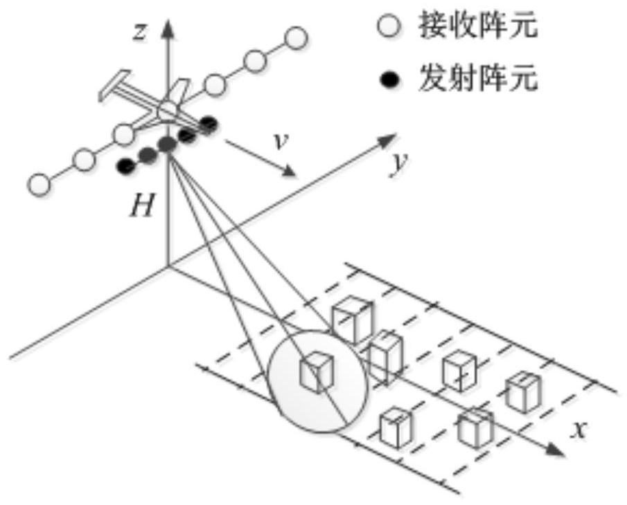
[0026] figure 1 A schematic diagram of the forward-looking array SAR system for earth observation is given. The carrier plane flies horizontally and uniformly along the direction of the observation strip at H meters above the observation strip, and the speed is v. The radar emission beam points to the front and bottom of the platform (using beam scanning to achieve effective coverage of the observation strip, figure 1 Examples of observations for the two-beam case are given). Assuming that the receiving and transmitting an...


PUM


Abstract

The invention discloses a sparse antenna of a forward-looking array SAR system, which comprehensively considers the sparse distribution of array elements, the system signal-to-noise ratio and the two-dimensional imaging quality, etc., and adopts a short dense and uniform transmitting array and a long sparse and uniform antenna. The basic configuration of the receiving array uses the zero point of the transmitting beam to suppress the receiving grating lobe and beam scanning to achieve effective coverage of the observation strip; it not only greatly reduces the number of array elements, but also has the following advantages: First, the transmitting antenna adopts a relatively The long array antenna forms a narrow beam, which improves the transmission gain, and the large receiving array element spacing also provides space for appropriately increasing the receiving array element gain, and finally improves the signal-to-noise ratio of the receiving echo; the second is that the transmitting narrow beam reduces the The scene width of each beam provides conditions for the adoption of a simple and efficient cross-course distance migration correction algorithm; third, the uniform arrangement of receiving array elements enables fast algorithms such as FFT to be used for cross-course imaging, which further improves the algorithm efficiency.

Description

technical field [0001] The invention belongs to the field of radar antenna design and signal acquisition, and relates to a sparse antenna of a forward-looking array SAR system. Background technique [0002] In the field of radar three-dimensional imaging, forward-looking array SAR has attracted the attention of many scientific research institutions and researchers in recent years. It uses a real-aperture array antenna for low-altitude and close-range earth observation of high-frequency (Ka, Ku, etc.) radars. Applications such as autonomous navigation and landing offer a new way to work 24 / 7. Forward-looking array SAR adopts matched filtering of broadband transmission signals to achieve high resolution in the range direction, uses beamforming of cross-course array antennas to achieve high resolution across directions, and uses virtual aperture synthesis of multiple pulses along the course to achieve high resolution along the course. Realize the three-dimensional imaging of ...

Claims


Application Information

Patent Timeline
Patent Type & Authority Patents(China)
IPC IPC(8): G01S7/03G01S13/90
CPCG01S7/03G01S13/90G01S13/9043
Inventor 刘向阳孟进杜宇扬申金山赵海燕刘许刚牛德智
Owner 中国人民解放军西安通信学院
Why Eureka
Try Eureka