DC fault ride-through method for power electronic transformer

A technology of DC fault ride-through and power electronics, applied in the direction of power transmission AC network, electrical components, emergency protection circuit devices, etc., can solve immature problems, achieve the effects of improving stability, reducing power supply reliability, and being easy to implement

Active Publication Date: 2018-04-20
XIAN XJ POWER ELECTRONICS TECH
View PDF2 Cites 16 Cited by
  • Summary
  • Abstract
  • Description
  • Claims
  • Application Information

AI Technical Summary

Problems solved by technology

At present, the low-voltage ride-through theory of interconnected devices, especially the low-voltage ride-through th

Method used


Image

  • DC fault ride-through method for power electronic transformer
  • DC fault ride-through method for power electronic transformer
  • DC fault ride-through method for power electronic transformer

Examples


Embodiment Construction

[0037] The present invention will be described in further detail below in conjunction with the accompanying drawings.

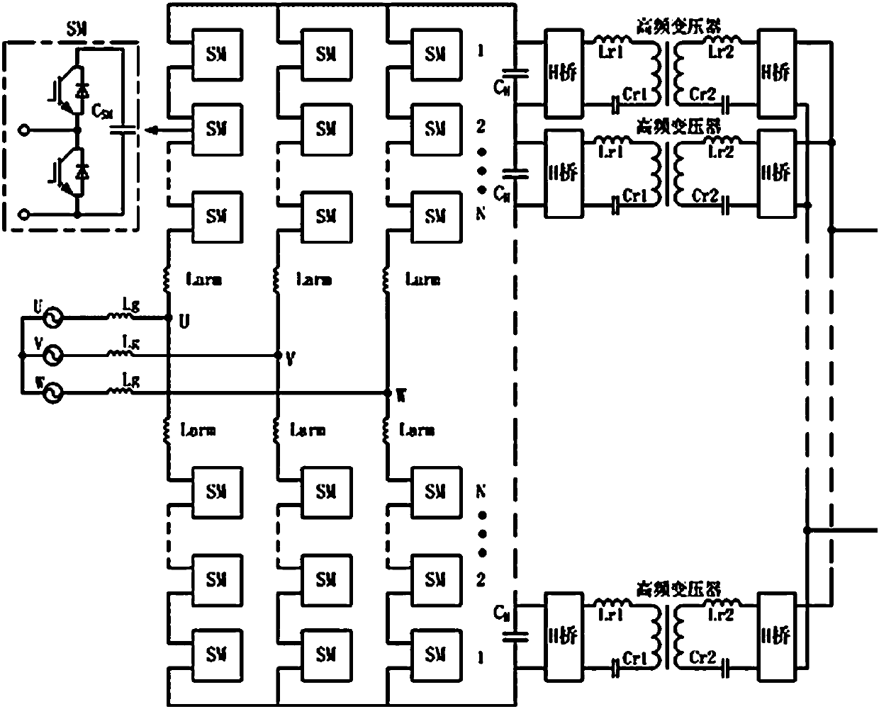
[0038] see figure 1 , the present invention adopts MMC+ISOP topology in the power electronic transformer main loop topology structure, each bridge arm of MMC topology is composed of a plurality of sub-modules connected in series, and the sub-module (SM) adopts a half-bridge structure; each group of power units of ISOP topology adopts Bidirectional LLC topology, each power unit includes a high-voltage side H-bridge module, a high-frequency isolation transformer, and a low-voltage side H-bridge module, where the high-voltage side modules are connected in series, and the low-voltage side modules are connected in parallel.

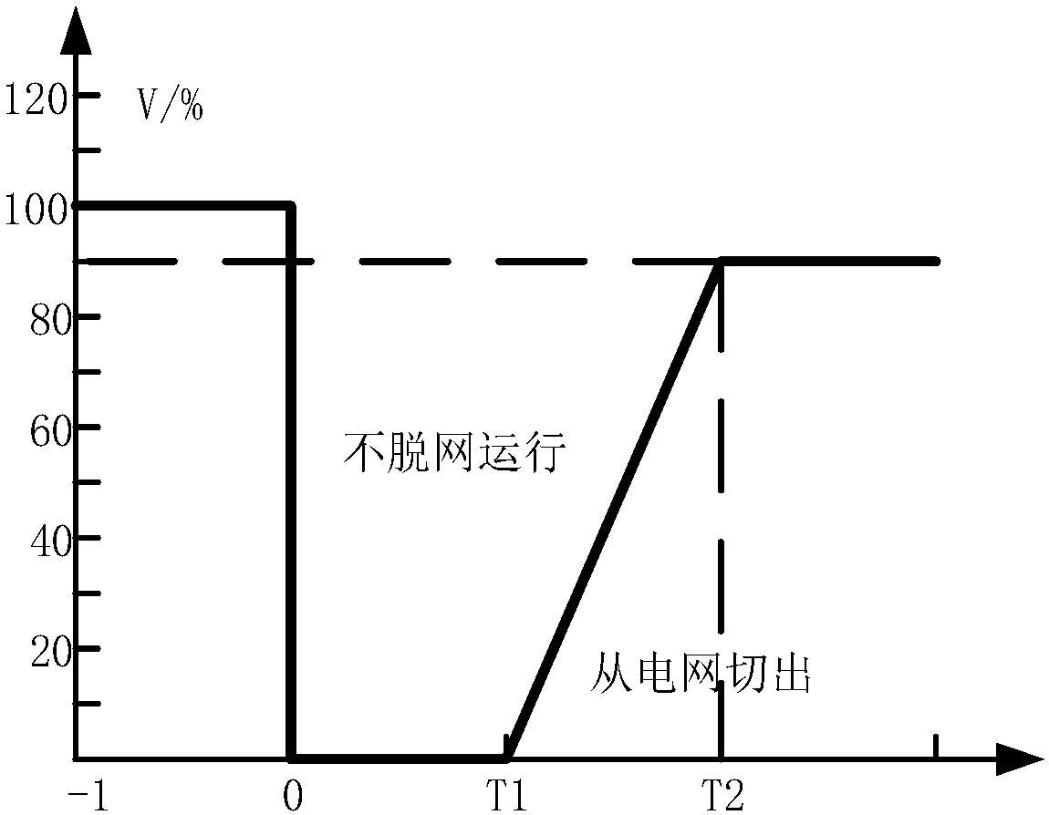
[0039] see figure 2 , T1 in the figure is taken as 0.5 seconds, and T2 is taken as 5.5 seconds. By coordinating the control functions of the MMC device and the DCDC device, the present invention realizes the fault ride-through function of t...


PUM


Abstract

The invention discloses a DC fault ride-through method for a power electronic transformer, and the power electronic transformer which is used for an AC-DC hybrid microgrid has two working modes: a voltage-stabilizing mode, i.e., a stabilizing a low-voltage side voltage; and a power mode, i.e., transmitting power to an AC power grid. When the power electronic transformer detects that the microgridhas a DC fault through the above two working modes, a DCDC device quickly locks a pulse, and calculates a to-be-provided short-circuit current according to a voltage drop value. An MMC device stabilizes an intermediate-stage bus voltage, and the DCDC device pulse is unlocked after the to-be-provided short-circuit current is calculated, a short-circuit support current is outputted till the bus voltage returns to a normal condition, and finally the working mode of the MMC device is switched to an operation mode before the fault, thereby completing the DC fault ride-through. The method can effectively improve the power supply quality of a microgrid system, and improves the stability of the microgrid system.

Description

technical field [0001] The invention belongs to the field of AC-DC hybrid micro-grid systems, and in particular relates to a DC fault ride-through method for power electronic transformers, aimed at improving the stability of the micro-grid system for power electronic transformers applied to AC-DC hybrid micro-grids. Background technique [0002] With the development of new energy, new power and new technologies, the advantages of DC power supply technology in certain fields are becoming more and more obvious. The traditional power grid needs to adapt to the access of a large number of distributed energy resources (DER) and energy storage systems (ES) with high penetration rates, and needs to effectively isolate the adverse impact of new energy on the AC power grid. Direct drive wind turbines, fuel cells, solar photovoltaics and other renewable energy generation methods must be incorporated into the AC distribution network through DC / AC inverter technology, and the extensive ...

Claims


Application Information

Patent Timeline
IPC IPC(8): H02J3/36H02J5/00H02H7/12
CPCH02H7/1213H02J3/36H02J5/00Y02E60/60
Inventor 郜亚秋王林安昱辛德锋曹建博陈雪梁燕张海龙
Owner XIAN XJ POWER ELECTRONICS TECH
Why Eureka
Try Eureka