
A Coiled Tubing Safety Mechanism

A safety mechanism and tubing technology, which is applied to drill pipes, casings, drill pipes, etc., can solve the problems that cannot be fully guaranteed, easily lead to dangerous accidents, and no tubing safety mechanism is found, so as to prevent the tubing string from falling into the well.

Inactive Publication Date: 2019-07-19
CHINA PETROLEUM & CHEM CORP +1
View PDF6 Cites 0 Cited by
  • Summary
  • Abstract
  • Description
  • Claims
  • Application Information

AI Technical Summary

Problems solved by technology

During the application process, oil pipe slipping, oil pipe falling and other phenomena are always the primary safety issues that need to be faced in on-site construction safety. At present, there is no safety mechanism specifically for coiled tubing injection devices. Generally, the pressure of the injector clamping cylinder is manually increased, so that Increase the friction to prevent the oil pipe from slipping. Always keep at least one observer standing near the wellhead to observe when working. If there is any phenomenon such as pipe string slipping, the operator should be notified in time to increase the pressure of the clamping cylinder. It cannot be fully guaranteed to make timely operations at the moment when the tubing slides, especially when the injector fails suddenly and the tubing string falls into the well, it is easy to cause dangerous accidents
[0003] After searching, no similar safety mechanism that can prevent the oil pipe from falling into the well was found

Method used


Image

  • A Coiled Tubing Safety Mechanism
  • A Coiled Tubing Safety Mechanism
  • A Coiled Tubing Safety Mechanism

Examples


Embodiment Construction

[0022] The detailed description and technical content of the present invention are described below with the accompanying drawings, but the accompanying drawings are only provided for reference and description, and are not intended to limit the present invention.

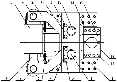
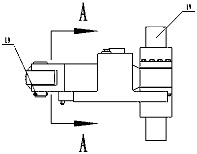
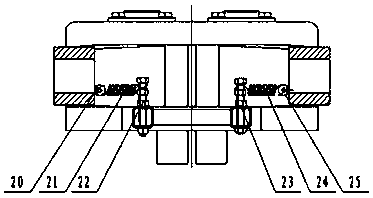
[0023] according to Figure 1-3 , a coiled tubing safety mechanism, mainly consists of a support seat 1, a right pin shaft 2, a right pin shaft baffle bolt 3, a right pin shaft baffle plate 4, a right arm 5, a right connecting shaft 6, a cylinder piston rod 7, and a cylinder cylinder Body 8, left connecting shaft 9, left arm 10, left pin baffle 11, left pin baffle bolt 12, left pin 13, left slip bolt 14, left slip 15, right slip 16, right Slip bolt 17, split pin 18, coiled tubing 19; left lifting screw 20, left spring 21, left spring bolt 22, right spring bolt 23, right spring 24, right lifting screw 25.

[0024] The right pin shaft 2 passes through the reserved hole on the support base 1 and the reserved hole on th...


PUM


Abstract

The invention discloses a coiled tubing safety mechanism. The coiled tubing safety mechanism comprises a supporting base, a left arm, a right arm, a left drilling slip and a right drilling slip, the middle of the left arm is hinged to the supporting base through a left pin roll, the middle of the right arm is hinged to the supporting base through a right pin roll, the left drilling slip is installed at the front end of the left arm, the right drilling slip is installed at the front end of the right arm, the left arm and the right arm are symmetrically arranged, the left drilling slip and the right drilling slip are symmetrically arranged, and the rear end of the left arm and the rear end of the right arm are hinged to a driving device simultaneously. By means of the coiled tubing safety mechanism, a tubular column can be quickly and tightly held when an injector breaks down, and a coiled tubing is prevented from falling to a well. Technical guarantee is provided for safe operation of the continuous oil tubing (or a compound tubing).

Description

technical field [0001] The invention relates to an oil pipe operation device, in particular to a coiled oil pipe safety mechanism. Background technique [0002] Coiled tubing equipment includes hydraulic station, injector, coiled tubing device and operating room. Coiled tubing coils are arranged on the coiled device and run into the well through the injector. Hydraulic power is provided, and personnel control the whole set of equipment in the operating room. During the application process, oil pipe slipping, oil pipe falling and other phenomena are always the primary safety issues that need to be faced in on-site construction safety. At present, there is no safety mechanism specifically for coiled tubing injection devices. Generally, the pressure of the injector clamping cylinder is manually increased, so that Increase the friction to prevent the oil pipe from slipping. Always keep at least one observer standing near the wellhead to observe when working. If there is any phe...

Claims


Application Information

Patent Timeline
Patent Type & Authority Patents(China)
IPC IPC(8): E21B19/22E21B19/10
CPCE21B19/10E21B19/22
Inventor 张国玉安百新刘红兰王进京曾凡春车传睿李德忠王昕任从坤张剑
Owner CHINA PETROLEUM & CHEM CORP
Learn More