sewer structure

A sewer and waterway technology, which is applied in the direction of cleaning sewer pipes, sewer pipe systems, waterway systems, etc., can solve the problems of rainwater discharge speed overflowing the wellhead, drowning, easy to be mixed with rainwater and piled up, so as to increase the probability of escape and prevent pedestrians The effect of falling into the well and reducing the accumulation of silt

Active Publication Date: 2020-06-30
东阳市君泰建筑工程有限公司
View PDF5 Cites 0 Cited by
  • Summary
  • Abstract
  • Description
  • Claims
  • Application Information

AI Technical Summary

Problems solved by technology

[0002] A large number of sewer structures will be set up on the existing roads. The sewers are used to collect rainwater in rainy days and drain the rainwater away. When the amount of rainwater is large, if the drainage system is poor, the rainwater is likely to overflow the wellhead due to insufficient discharge speed. situation, lack of auxiliary drainage system;
[0003] Moreover, since the water inlet end of the sewer is only sealed by a manhole cover, and the manhole cover is fixedly installed through the wellhead, if the manhole cover is easy to be stolen or washed away, it is easy to cause the situation of falling into the well, and it cannot be cleaned in time after falling into the well. Climbing out, causing safety accidents such as drowning;
[0004] Finally, because a lot of dust and other debris will enter the sewer, it is easy to mix with rainwater and accumulate on the bottom of the sewer. The accumulated silt will cause the drainage space of the sewer to become smaller, the drainage speed will be reduced, and the situation of overflow will be more likely to occur

Method used


Image

  • sewer structure
  • sewer structure
  • sewer structure

Examples


Embodiment Construction

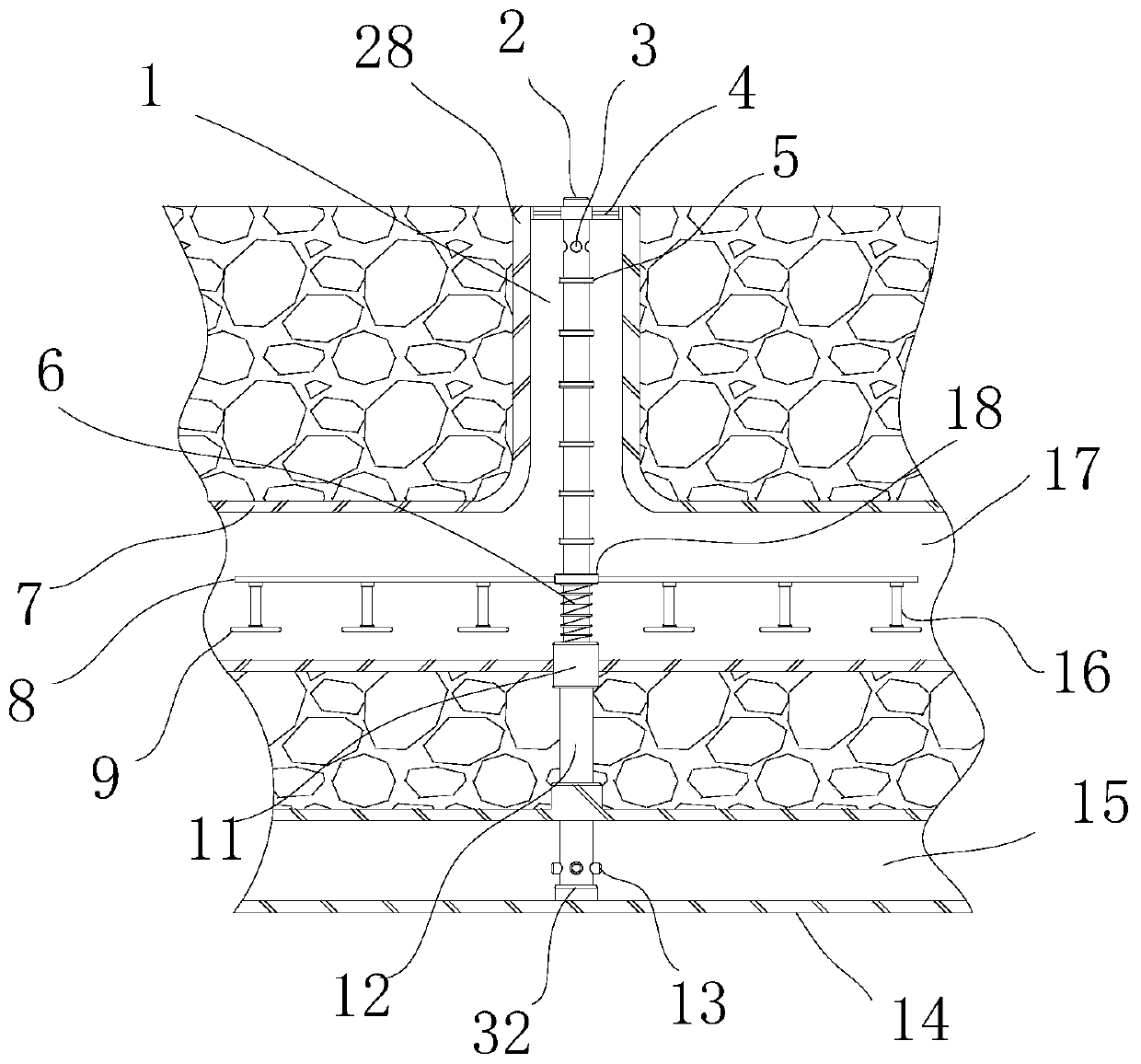
[0024] Such as figure 1 As shown, the sewer structure includes a first sewer pipe 7 arranged at the bottom of the road and a second sewer pipe 14 arranged at the bottom of the first sewer pipe 7. The first sewer pipe 7 and the second sewer pipe 14 are parallel to each other. The sewer pipe 7 is provided with a first sewer 17, the second sewer pipe 14 is provided with a second sewer 15, and the top of the first sewer pipe 7 is vertically provided with more than one inlet pipe 28, and the middle of the inlet pipe 28 is provided with the first sewer. 17 are connected to the access channel 1, the upper end surface of the access channel 1 is open, and a well cover 4 is installed at the upper open end;

[0025] Insert an auxiliary drain pipe 2 into the channel 1, the bottom of the auxiliary drain pipe 2 passes through the positioning sleeve 11 at the bottom of the first sewer pipe 7 and inserts it into a connecting pipe 12, and one end of the connecting pipe 12 is sealed into the I...


PUM


Abstract

The invention discloses a sewer structure. The sewer structure comprises a first sewer pipe arranged at the bottom of a road and a second sewer pipe arranged at the bottom of the first sewer pipe, thefirst sewer pipe and the second sewer pipe are parallel to each other, a first sewer is arranged in the first sewer pipe, a second sewer is arranged in the second sewer pipe, one or more inflow pipesare vertically arranged at the top of the first sewer pipe, an inflow channel communicating with the first sewer is arranged in the middle of each inflow pipe, the upper end face of each inflow channel is opened, and a well lid is installed at the upper opened end of each inflow channel. An auxiliary drainage pipe is arranged in each sewer opening, the auxiliary drainage pipes are used for solving the problem that water overflows from wellheads when the drainage amount is large, safety can be greatly improved, sludge can be prevented from being accumulated, and the drainage environment of thesewers is improved.

Description

technical field [0001] The invention relates to the field of sewers, in particular to a sewer structure. Background technique [0002] A large number of sewer structures will be set up on the existing roads. The sewers are used to collect rainwater in rainy days and drain the rainwater away. When the amount of rainwater is large, if the drainage system is poor, the rainwater is likely to overflow the wellhead due to insufficient discharge speed. situation, lack of auxiliary drainage system; [0003] Moreover, since the water inlet end of the sewer is only sealed by a manhole cover, and the manhole cover is fixedly installed through the wellhead, if the manhole cover is easy to be stolen or washed away, it is easy to cause the situation of falling into the well, and it cannot be cleaned in time after falling into the well. Climbing out, causing safety accidents such as drowning; [0004] Finally, because a lot of dust and other debris will enter the sewer, it is easy to mix...

Claims


Application Information

Patent Timeline
Patent Type & Authority Patents(China)
IPC IPC(8): E01F5/00E03F3/02E03F9/00
CPCE01F5/00E03F3/02E03F9/00
Inventor 金丽丽
Owner 东阳市君泰建筑工程有限公司
Why Eureka
Try Eureka