Connecting rod tooth form and machining method thereof

A processing method and technology of tooth shape, applied in the field of reciprocating connecting rod processing, can solve the problems of insufficient meshing contact area, large processing stress, different tooth shape precision, etc., to reduce distance variation, high processing efficiency, and tooth shape. The effect of high precision and stability

Active Publication Date: 2018-04-27
临沂草之美医药科技有限公司
View PDF8 Cites 1 Cited by
  • Summary
  • Abstract
  • Description
  • Claims
  • Application Information

AI Technical Summary

Problems solved by technology

This processing method usually adopts double forming grinding wheel grinding technology, and uses a diamond roller to dress the forming grinding wheel. When dressing the forming grinding wheel, the main shaft of the grinding head in a cantilever state must move laterally. Different rigidity makes the tooth shape accuracy copied on different forming grinding wheels different; and the rough and fine grinding of the two-stage tooth shape is completed in one clamping of the workpiece, and the processing stress generated is relatively large, so the tooth shape accuracy The stability of the distance accuracy with the second-stage tooth profile is not high
[0006] The common defect of the two processing methods of form milling and form grinding is that before machining the tooth shape, the connecting rod must be separated at the tooth shape position to become the connecting rod body and the connecting rod cover, and then the separated surface should be finished, that is, pre-machining Milling or grinding the tooth shape after leaving the tooth top plane, so there are many processes and low efficiency
[0007] Wire-cut tooth shape is to use CNC wire-cutting machine tool to wire-cut the tooth shape of the connecting rod body and the connecting rod cover at the same time according to the tooth shape accuracy requirements, and then grind (mill) the tooth top plane. The defect of this method is: wire cutting The processing stress inside the rear connecting rod body and connecting rod cover is released, resulting in stress deformation, and the distance between the two tooth profiles changes by ≥0.02mm, and the tooth profile surface has microscopic vibration lines, so that the meshing contact area does not reach 80 % requirements

Method used


Image

  • Connecting rod tooth form and machining method thereof
  • Connecting rod tooth form and machining method thereof
  • Connecting rod tooth form and machining method thereof

Examples


Embodiment Construction

[0027] The present invention will be further described below in conjunction with specific embodiment:

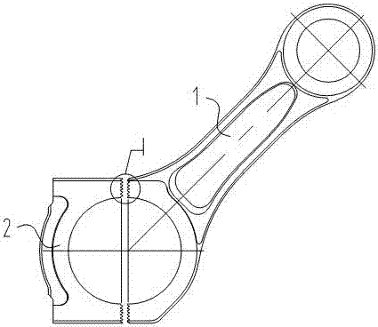
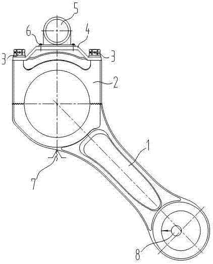
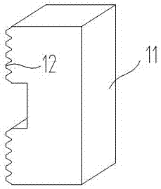
[0028] Figure 1-Figure 6 Middle: 1. Connecting rod body, 1.1, Arc position line of dedendum, 1.2, Center line of large hole of connecting rod body, 2. Connecting rod cover, 2.1, Center line of large hole of connecting rod cover, 3. Connecting rod bolt, 4 , connecting frame, 5, vibrator, 6, screw, 7, adjustable positioning, 8, small head mandrel, 9, tooth top plane of connecting rod body, 10, forming fine grinding wheel, 10.1, tooth root plane, 11, Diamond dressing block, 12, trimming block tooth profile plane.

[0029] figure 1 A top view shows the state of a connecting rod with an oblique cut on the wire cutting machine. The connecting rod includes a connecting rod body 1 and a connecting rod cover 2. The wire cutting tooth shape has been completed. For the convenience of illustration, the connecting rod is slightly separated. The two-stage teeth on the body 1 and the c...


PUM


Abstract

The invention discloses a connecting rod tooth form and a machining method thereof and relates to the technical field of reciprocating connecting rod machining. The machining method comprises the steps that firstly, linear cutting of tooth forms of a connecting rod body and a connecting rod cover is conducted through a linear cutting machine tool, wherein the finish grinding amount is reserved foreach linear cutting tooth form; then, the tooth forms of the connecting rod body and the connecting rod cover are ground through a forming finish grinding wheel on a forming grinding machine; and destressing treatment is conducted on the tooth forms of the connecting rod body and the connecting rod cover between the step of linear cutting of the tooth forms and the step of forming finish grindingof the tooth forms. By means of the machining method, machining stress generated in all procedures including that before finish grinding can be reduced; distance variation between every two tooth forms is reduced; precision stability of the tooth forms is improved, and thus it is guaranteed that the engagement contact area of every two tooth forms reaches 80%; and in addition, each tool top planeis ground while finish grinding of the tooth forms is conducted, the procedures that the connecting rod body is separated from the connecting rod cover, and then finishing machining of each separation face is conducted are omitted, and machining efficiency is high.

Description

technical field [0001] The invention belongs to the technical field of reciprocating connecting rod processing, and mainly relates to a processing method for connecting rod tooth profile. Background technique [0002] The connecting rod is an important part connecting the piston and the crankshaft in the reciprocating piston internal combustion engine. The basic structure of the connecting rod is as follows: figure 1 As shown, the large hole of the connecting rod is divided into two, and the cut is divided into flat cut and oblique cut. The two semicircular holes of the connecting rod body and the connecting rod cover are combined into the large hole of the connecting rod. The two-stage tooth profile positioning separated by the diameter and size of the large hole has reliable positioning and compact structure, but it requires high tooth profile accuracy. The roughness of the tooth profile meshing surface is Ra≤1.6μm. The machining accuracy of the angle and tooth spacing mu...

Claims


Application Information

Patent Timeline
Patent Type & Authority Applications(China)
IPC IPC(8): B23P15/14
CPCB23P15/14
Inventor 薛璐浩
Owner 临沂草之美医药科技有限公司
Why Eureka
Try Eureka