Permanent-magnet synchronous engraving and milling electric spindle adopting internal cooling for shaft core

A technology of permanent magnet synchronization and electric spindle, which is applied in the direction of large fixed members, metal processing machinery parts, maintenance and safety accessories, etc. It can solve the problems of long time for manual polishing, thermal elongation of the spindle and insufficient fineness, etc., and achieve reliable The effect of machining target, stable bearing temperature and low cost

Pending Publication Date: 2019-12-13
广州飞速尔精密部件有限公司 +1
View PDF0 Cites 4 Cited by
  • Summary
  • Abstract
  • Description
  • Claims
  • Application Information

AI Technical Summary

Problems solved by technology

Due to the problems of spindle speed and thermal elongation of the existing domestically produced CNC machine tools, the processing fineness is not enough, the manual polishing takes a long time, and the efficiency is low and the cost is high.
[0004] Some high-precision mold parts can only be processed by imported high-precision CNC machine tools, which costs a lot
The use of high-precision, high-speed, low-heat elongation electric spindles for CNC machine tools is the key to improving the precision of forming surface processing. However, my country lacks such electric spindle products, and foreign technology is strictly protected, and the technology is basically mastered in the CNC production of several molds in Japan and Europe. Enterprises, my country's machine tool enterprises are short of such machine tool products, and urgently need to solve the technical problems of the above-mentioned high-speed low-heat elongation electric spindle

Method used


Image

  • Permanent-magnet synchronous engraving and milling electric spindle adopting internal cooling for shaft core
  • Permanent-magnet synchronous engraving and milling electric spindle adopting internal cooling for shaft core
  • Permanent-magnet synchronous engraving and milling electric spindle adopting internal cooling for shaft core

Examples


Embodiment Construction

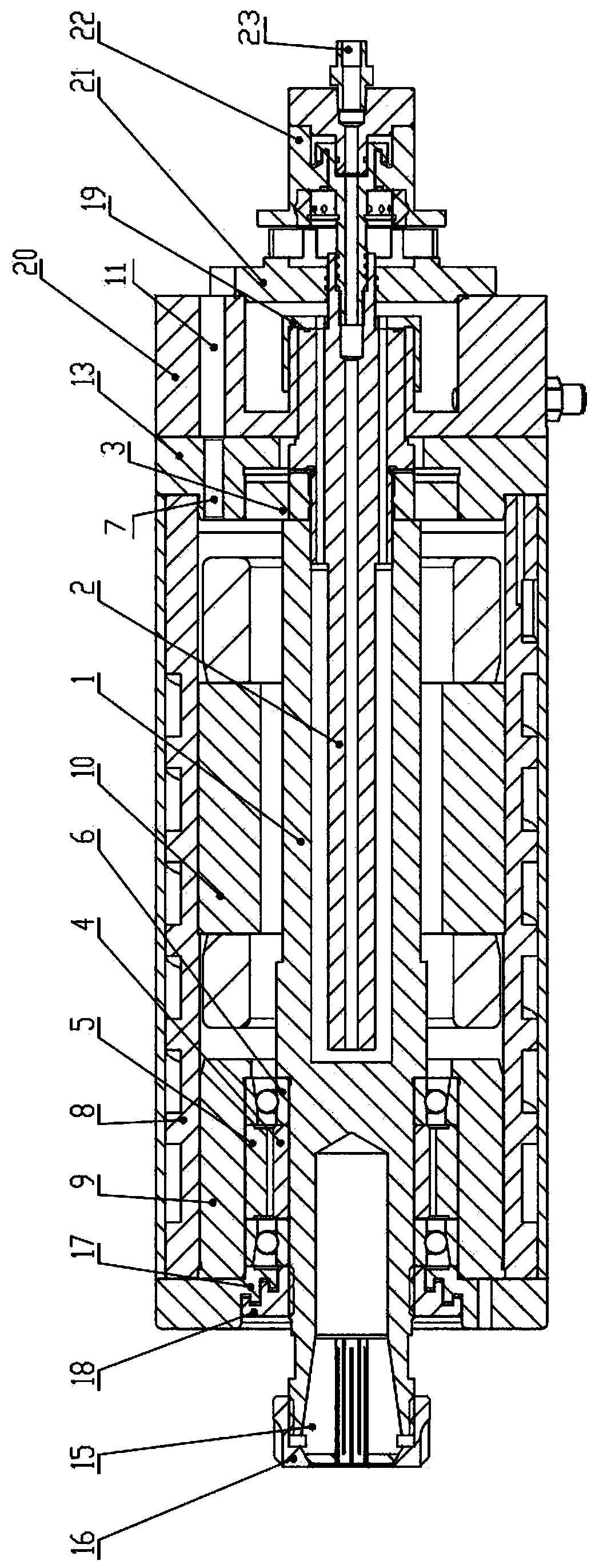
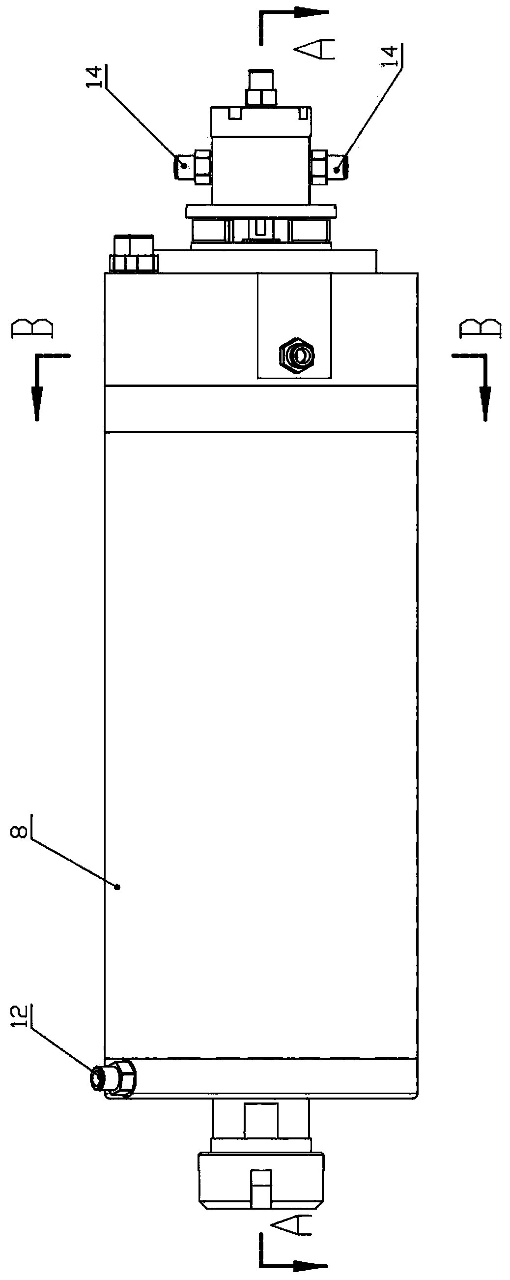
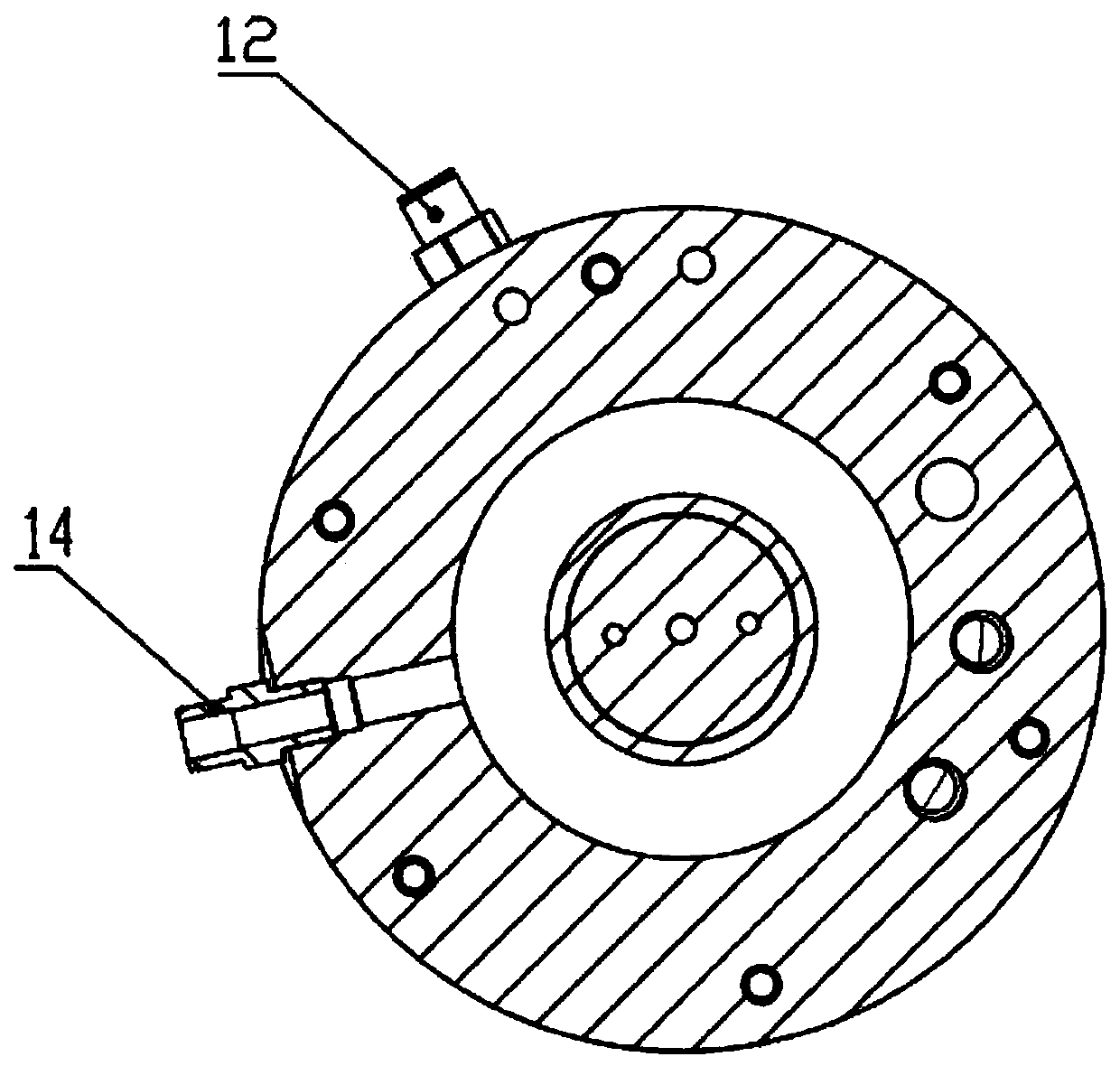
[0022] Shown in the accompanying drawings, the present invention is further described:

[0023] Such as figure 1 , figure 2 , image 3 and Figure 4 As shown, among them, figure 1 figure 2 A-A sectional view of the section, image 3 yes figure 2 The B-B cross-sectional view, Figure 4 is the end view of the electric spindle. The technical purpose of the present invention is to overcome the problems that the thermal elongation of the spindle core of the engraving and milling electric spindle is not well controlled and the precision of the spindle fluctuates with temperature changes. The specific technical solution is as follows: the design is a built-in rare earth permanent magnet synchronous high-speed motor-driven spindle, including a rotatable spindle core 1, a liquid splitting shaft 2 for cooling the spindle core 1, and a support for the spindle core 1. The rear bearing 3 and the front bearing 6, the water jacket housing 8 for cooling the stator 10 and the inner...


PUM


Abstract

The invention provides a permanent-magnet synchronous engraving and milling electric spindle adopting internal cooling for a shaft core, and belongs to a vertical engraving and milling electric spindle. The electric spindle comprises a rotatable main shaft core, a liquid flow distribution rotary shaft used for cooling the main shaft core, a rear bearing and a front bearing which are used for supporting the main shaft core, a water jacket shell body used for cooling a stator and the bearings, a front pipe joint used for air curtain protection, and a liquid backflow and reduced-pressure recoverybox used for the flowing of a cooling liquid. According to the scheme, a spindle installation structure with vertical layout is adopted, simultaneous temperature control cooling is carried out on thestator and a rotor of a motor, the same cooler or two coolers can be used for the stator and the rotor, and temperature management is carried out on heating parts of the spindle, so that accuracy management in the length direction of the spindle is realized, and high-precision machining is achieved. The electric spindle is an electric spindle with controllable thermal elongation and high accuracyand reliability, and has the advantages of being simple in structure, stable and reliable in working, and the like.

Description

technical field [0001] The invention belongs to a vertical engraving and milling electric spindle, in particular to a permanent magnet synchronous engraving and milling electric spindle with internal cooling in the shaft core. Background technique [0002] At present, there are two main ways to achieve three-dimensional forming surface processing in the precision mold industry: one is to use CNC machine tools for three-dimensional engraving and milling, and then manually polish the surface; The profiled surface is machined by EDM and polished by hand. [0003] The above two methods have a CNC engraving and milling process, and the processing quality of the engraving and milling process directly determines the workload of the subsequent manual process. Due to the spindle speed and spindle thermal elongation of the existing domestically produced CNC machine tools, the processing fineness is not enough, the manual polishing takes a long time, and the efficiency is high and the...

Claims


Application Information

Patent Timeline
Patent Type & Authority Applications(China)
IPC IPC(8): B23B19/02B23Q11/12
CPCB23Q1/70B23Q11/126
Inventor 徐致雄刘建锋
Owner 广州飞速尔精密部件有限公司
Why Eureka
Try Eureka