Connecting joint for H-shaped steel beam and steel reinforced concrete beam and manufacturing method

A technology of concrete beams and connecting nodes, which is applied in the direction of architecture and building construction, and can solve problems such as node connection

Pending Publication Date: 2018-04-27
北京万兴建筑集团有限公司 +1
View PDF8 Cites 0 Cited by
  • Summary
  • Abstract
  • Description
  • Claims
  • Application Information

AI Technical Summary

Problems solved by technology

[0003] The invention provides a connection node and method of H-shaped steel beams and steel-concrete beams to s

Method used


Image

  • Connecting joint for H-shaped steel beam and steel reinforced concrete beam and manufacturing method
  • Connecting joint for H-shaped steel beam and steel reinforced concrete beam and manufacturing method
  • Connecting joint for H-shaped steel beam and steel reinforced concrete beam and manufacturing method

Examples


Embodiment Construction

[0014] The specific implementation manners of the present invention will be further described in detail below in conjunction with the accompanying drawings and examples. The following examples are used to illustrate the present invention, but are not intended to limit the scope of the present invention.

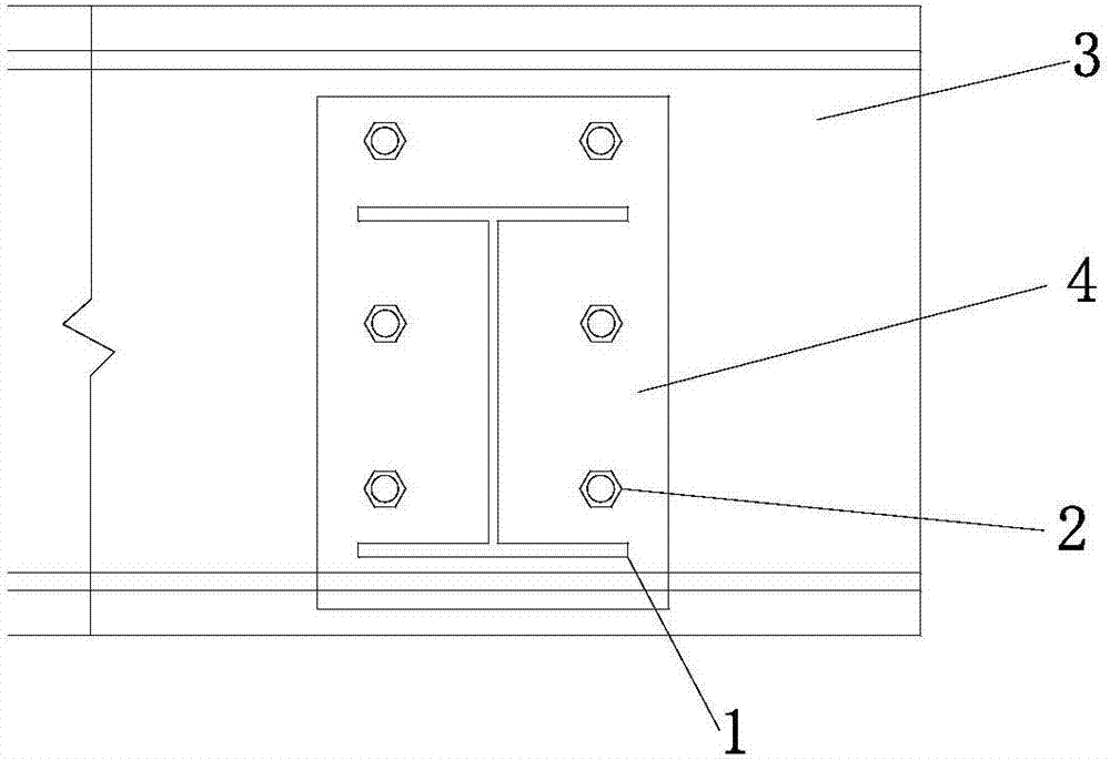
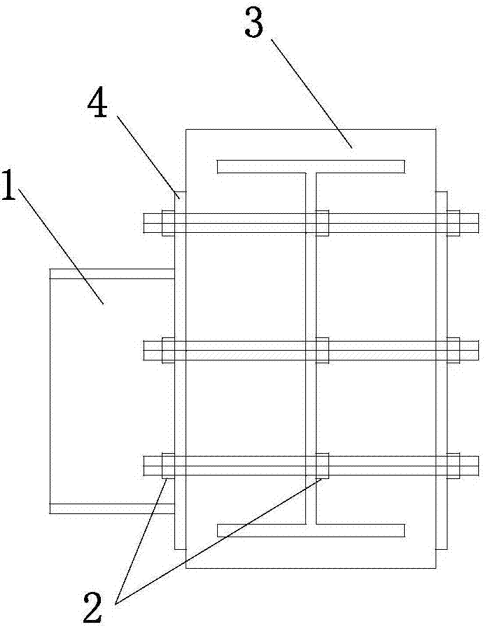
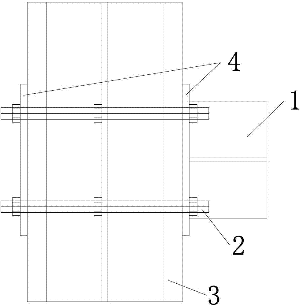
[0015] Such as Figure 1-4 Shown, a connection node and method of H-shaped steel beam and steel concrete beam, its construction method is as follows:

[0016] In the first step, when the concrete structure is constructed to a certain height, the steel concrete is pre-embedded in the concrete beams that need to be connected with the H-shaped steel beams.

[0017] The second step is to pre-embed the high-strength bolt rods in the holes drilled on the steel keel, and fix them with nuts on the inner side of the web of the steel keel to prevent the high-strength bolt rods from slipping or even being pulled out in the concrete when they are stressed. out.

[0018] The third step...


PUM


Abstract

The invention discloses a connecting joint for an H-shaped steel beam and a steel reinforced concrete beam and a manufacturing method, and belongs to the technical field of architectural engineering.The joint structure comprises an H-shaped steel beam, high-strength bolt rods, a steel reinforced concrete beam and rectangular joint plates. The high-strength bolt rods are pre-embedded into the steel reinforced concrete beam, the two ends of each high-strength bolt stretch out, the stretching-out portions are connected with rectangular joint plates with holes and fastened through nuts, when the H-shaped steel beam is hoisted, one end of the H-shaped steel beam abuts against the rectangular joint plates, and the H-shaped steel beam and the rectangular joint plates are connected through a welding line. Compared with the prior art, the assembling mode is simple, the application range is wide, the anchoring strength is reliable, the influence on an original structure is small, the steel quantity is small, and the comprehensive cost is low. The connecting joint is applicable to connection of the H-shaped steel beam and the steel reinforced concrete beam.

Description

technical field [0001] The invention belongs to the technical field of construction engineering, and relates to a connection node between an H-shaped steel beam and a steel-concrete beam and a method thereof. Background technique [0002] In recent years, there are more and more high-rise and super high-rise buildings in my country, and the architectural shapes are also changing with each passing day. Many high-rise and ultra-high-rise buildings have been designed to highlight the building's facade shape and expand the upper use space. Many high-altitude cantilevered cast-in-place concrete structures have appeared, and there are some structures with large cantilevered spans. In order to facilitate the construction of these cantilevered structures, a cantilevered construction platform is usually built 1-2 floors below it, among which there is a space steel truss stress system with a height of one floor. Due to the large load of the high-altitude cantilevered structure, the r...

Claims


Application Information

Patent Timeline
IPC IPC(8): E04B1/30E04B1/58
CPCE04B1/185
Inventor 曹万林张元吕宝山高腾李金水刘苹
Owner 北京万兴建筑集团有限公司
Why Eureka
Try Eureka