Composite material space truss joint and method

A technology of composite materials and connecting nodes, which is applied in the direction of architecture and building construction, etc., can solve the problems of inability to exert high strength of composite materials, weakening of composite material pipe sections, and unguaranteed bearing capacity, and achieve comprehensive node connection forms and low assembly costs. Low, the effect of reducing the direct contact area

Active Publication Date: 2013-11-20
SOUTHEAST UNIV
View PDF7 Cites 7 Cited by
  • Summary
  • Abstract
  • Description
  • Claims
  • Application Information

AI Technical Summary

Problems solved by technology

At present, the joint efficiency of traditional connection nodes of composite material profiles in this field, such as cemented connection, mechanical connection and their mixed connection, is less than 30%, which is far from being able to take advantage of the high strength of composite materials
Recently, some new composite circular pipe connection nodes have appeared. The principle is mainly to increase the bearing capacity by applying pre-tightening force to the joints. However, the creep of composite materials is very serious under the continuous action of high stress. As the creep progresses, The preload will gradually decrease, and the bearing capacity cannot be guaranteed
There are also some new types of joints that drill threads at composite material joints and then connect them through threads. This form improves the bearing capacity to a certain extent, but the process of drilling threads at composite material pipe joints is more complicated, and the composite The cross-section of the material tube is weakened, in addition, this form is only suitable for composite material round tubes, but not for composite material square tubes

Method used


Image

  • Composite material space truss joint and method
  • Composite material space truss joint and method
  • Composite material space truss joint and method

Examples


Embodiment 1

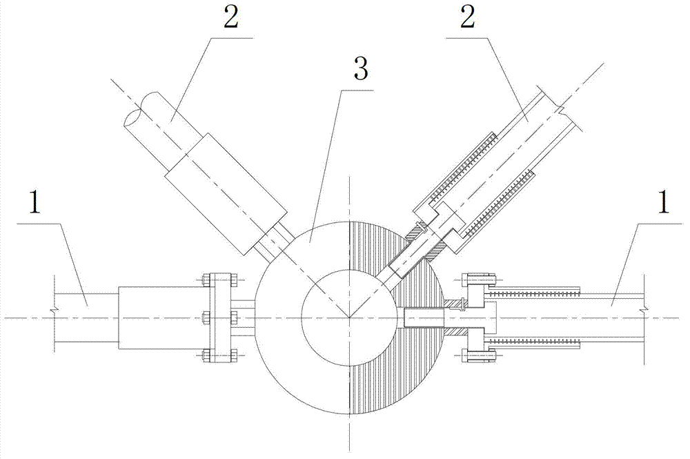
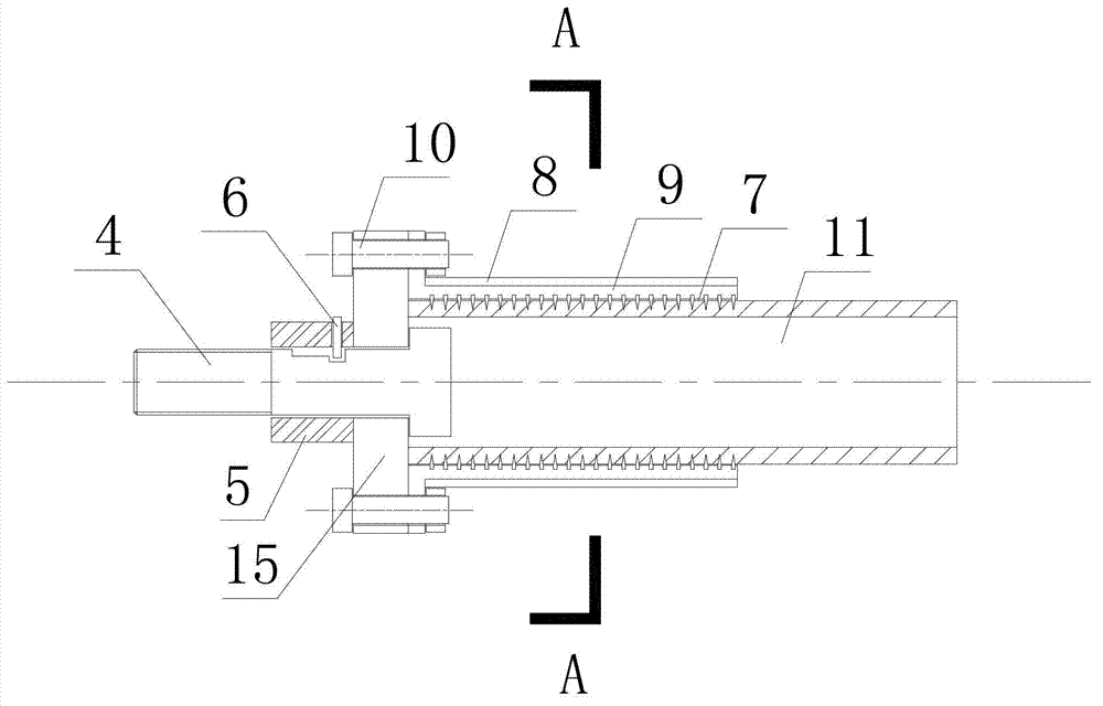
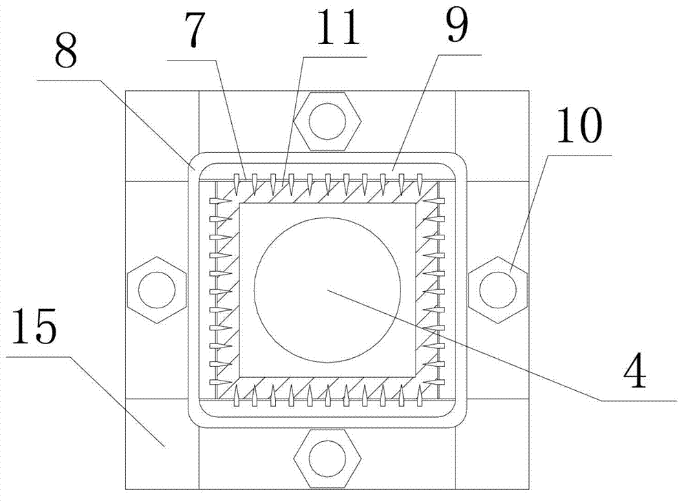
[0043] see figure 1 , figure 2 , image 3 , Figure 4 , Figure 5 , Figure 6 and Figure 7 Shown:

[0044] Firstly, after coating the thorny surface of the thorn plate 9 with flange with epoxy resin glue, place it under the pressurization equipment, press the first steel thorn of the thorn plate 9 into the outer surface of the composite material square tube 11 with the pressurization equipment ; Repeat the above-mentioned process, complete the pressing of the first steel thorns of the remaining three flange thorns 9 one by one, and wrap the aramid fiber cloth 8 impregnated with epoxy resin glue 7 on the outer surface of the discrete thorns 9. Discrete thorn plates with flanges 9 are bound together as a whole; one end of the high-strength bolt 4 is connected to the first bolt hole in the middle of the sealing plate 15, and then the sleeve 5 and the pin 6 are installed on the protruding bolt rod. Then, the four discrete flanges are connected to the sealing plate 15 with...


PUM


Abstract

The invention discloses composite material space truss joint and method. The composite material space truss joint comprises composite material square tube connectors, composite material circular tube connectors and a bolt-sphere joint. The composite material square tube connectors and the composite material circular tube connectors are connected with the bolt-sphere joint through high-strength bolts. The composite material space truss joint covers reliable connection of two closed sections of most frequently used circular tubes and square tubes in the space truss structure, joint form is complete, and the problem of the joint of the composite material closed sections in the application of the space truss structure is basically solved. Steel slabs and the cementitious composite connecting mode can provide joint strength as required in the structure, and the advantages of high strength of composite materials can be effectively exerted. Winding of aramid fiber cloth helps improve the overall performance of the joint, so that the joint strength is further improved, and anti-corrosion area in joint regions are reduced. Joint production is completed in factories that guarantee production precision, on-site assembly is fast, assembly fee is low, and time limit is short. Prestress application is omitted during the production, and bearing capacity degradation caused by creep of the composite materials is no need to worry about.

Description

technical field [0001] The invention belongs to the technical field of civil engineering and relates to a connection node and a method for a grid frame made of composite materials. Background technique [0002] With the enhancement of my country's economic strength and the acceleration of the urbanization process of the population, people have more and more demands for large-span spatial structures, and the requirements are also constantly improving. As we all know, there is a limit to the span of a building with a certain structural form of a specific building material. The current large-span buildings mostly use steel, and the maximum span of the completed buildings can reach more than 200 meters. To break through this span limit, use high-strength, light-weight fiber-reinforced composite materials, and reasonably select the form of grid structure. feasible way. Fiber-reinforced composite materials have many superior properties such as high specific strength, large speci...

Claims


Application Information

Patent Timeline
Patent Type & Authority Applications(China)
IPC IPC(8): E04B1/58
Inventor 吴刚
Owner SOUTHEAST UNIV
Why Eureka
Try Eureka