Electromagnetic actuator

Active Publication Date: 2018-05-01
DENSO CORP
View PDF15 Cites 0 Cited by
  • Summary
  • Abstract
  • Description
  • Claims
  • Application Information

AI Technical Summary

Problems solved by technology

The coil generates a magn

Method used


Image

  • Electromagnetic actuator
  • Electromagnetic actuator
  • Electromagnetic actuator

Examples


Example

[0020] (First embodiment)

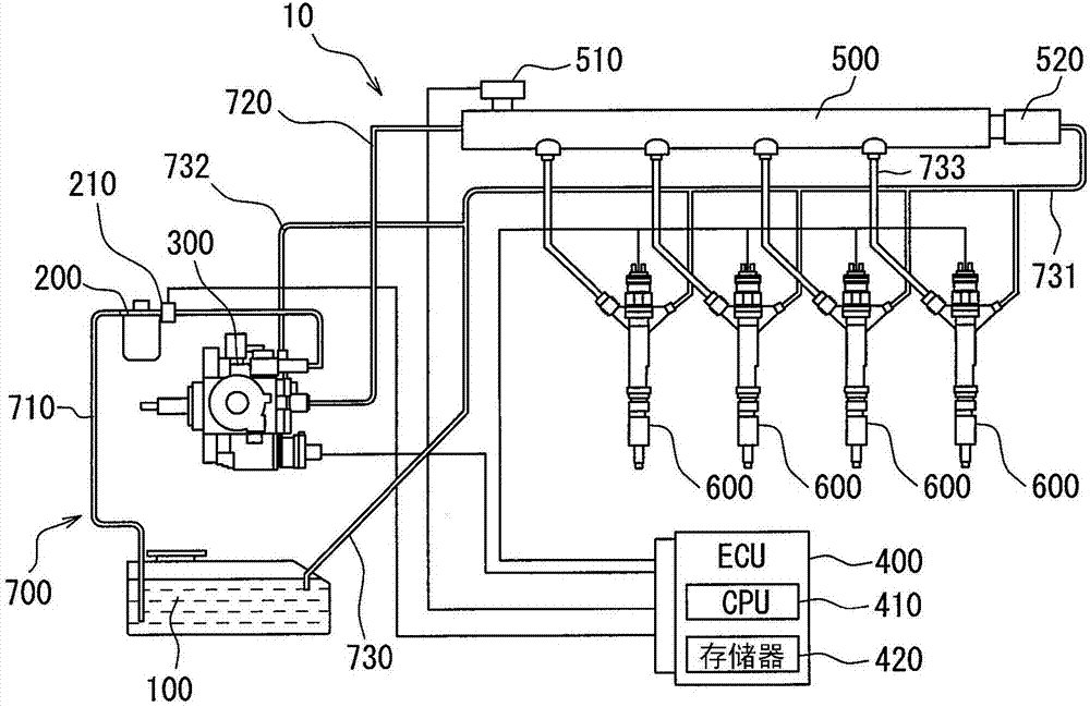
[0021] reference Figure 1 to 9 , The first embodiment will be described below. Such as figure 1 As shown, the fuel supply system 10 according to the first embodiment is a fuel supply system for a diesel engine. The fuel supply system 10 includes a fuel tank 100, a fuel filter 200, a supply pump 300, an ECU 400, a common rail 500, and a fuel injection valve 600.

[0022] The fuel tank 100 is a tank that stores fuel to be supplied to the internal combustion engine. The fuel tank 100 and the supply pump 300 are connected by a pipe 700 for fuel. The fuel stored in the fuel tank 100 is pumped by the supply pump 300. The supply pump 300 pumps fuel from the fuel tank 100 and supplies the fuel to the common rail 500. The fuel remaining in the fuel injection valve 600 and the common rail 500 (main return fuel) and fuel from the feed pump 300 (pump return fuel) are returned to the fuel tank 100 from the pipe 700 as return fuel.

[0023] The pipe 700 includes a...


PUM


Abstract

The present disclosure provides an electromagnetic actuator (30) that drives an armature (33) by an electromagnetic force. The electromagnetic actuator (30) includes a stator (82), a coil (81), and aninsulator (84). The stator (82) is formed of a magnetic material and has a cylindrical portion. The coil (81) is disposed outside of the stator (82). The coil (81) generates a magnetic field when being energized. The insulator (84) is disposed in a particular region of the stator (82) facing the coil (81) in a radial direction. The insulator (84) extends partially along the stator (82) in a circumferential direction and suppresses a current flowing through the stator (82) in the circumferential direction. The stator (82) is continuously formed entirely along the circumferential direction by the magnetic material.

Description

technical field [0001] The present disclosure relates to an electromagnetic actuator that drives an armature by electromagnetic force. Background technique [0002] Typically, an electromagnetic actuator includes a coil that, when energized, generates a magnetic field. An inner stator is arranged inside the coil, and an eddy current is generated on the side of the inner stator close to the coil after electrification. The eddy currents create a magnetic field that cancels the magnetic field generated by the coil. As a result, the magnetic field generated by the eddy current may interfere with the action of the armature. [0003] For example, patent document (DE10235240A) discloses a method for suppressing the occurrence of eddy currents. More specifically, this patent document discloses a slit extending in the axial direction over the entire area composed of magnetic material. In this way, the magnetic material is entirely separated by the slit. Since the current is cut ...

Claims


Application Information

Patent Timeline
IPC IPC(8): F02M51/06
CPCF02M51/0628H01F7/1638H01F2007/1676H02K1/34H02K3/28H02K3/30H02K33/02
Inventor 佐佐和也足立尚史木谷慎吾
Owner DENSO CORP
Why Eureka
Try Eureka