Medical equipment supporting device

A supporting device and medical equipment technology, which is applied in the direction of mechanical equipment, supporting machines, machine tables/brackets, etc., can solve problems such as inability to achieve locking and fixing, inability to ensure work stability, and influence on angle and height changes of triangular frame structures. Achieve the effects of reducing bump damage, reducing movement, and reasonable structural design

Inactive Publication Date: 2018-05-01
冷雪斐
View PDF1 Cites 3 Cited by
  • Summary
  • Abstract
  • Description
  • Claims
  • Application Information

AI Technical Summary

Problems solved by technology

[0002] The placement and protection of medical equipment is an issue that major hospitals attach great importance to. In order to enhance the maintenance of medical equipment and reduce unnecessary damage during use, staff need to be careful in the process of transporting medical equipment. Due to modern medical equipment The supporting device of the medical equipment cannot protect the medical equipment well and reduce the damage to the equipment to the greatest extent, so the supporting device of the medical equipment needs to be further improved. To solve this problem, a medical equipment support with the announcement number CN206786286U The device is designed with a screw rod, turnbuckle and clamping block. Since the first telescopic rod cannot be locked and fixed at a certain height, it will affect the angle and height changes of the triangular frame structure. Guarantee better work stability, so it needs to be improved

Method used


Image

  • Medical equipment supporting device
  • Medical equipment supporting device
  • Medical equipment supporting device

Examples


Embodiment Construction

[0014] Attached below figure 1 - attached Figure 7 The present invention is described in detail below.

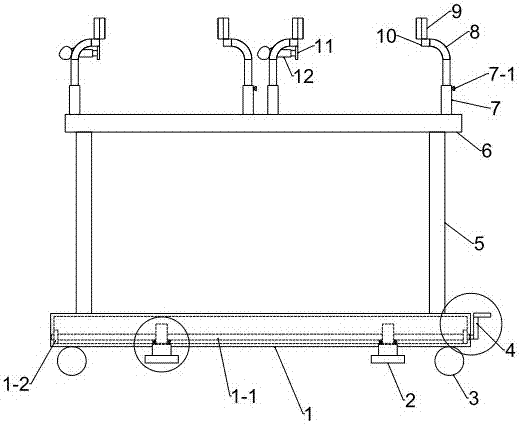
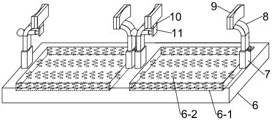
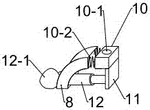
[0015] like Figure 1-Figure 7 As shown, the present invention includes a base 1, a support seat 2, a support plate 6, an air bag 12-1 and a hand 4, the base 1 is a cavity structure and its lower end surface is provided with four universal wheels 3, the inside of the base 1 A shaft 1-1, a fixed disc 1-2 and a cam 1-3 are provided. There are two shafts 1-1 and each shaft 1-1 is sleeved with two fixed discs 1-2 and two cams 1-3. 3. The two shafts 1-1 are respectively located near the front and rear universal wheels 3 of the base 1. Both ends of the shaft 1-1 pass through the inner wall of the base 1 and the distance through the inner wall is 2 / 3 of the wall thickness of the base 1. The wall thickness of base 1 is about 50mm, and fixed plate 1-2 is close to the inner wall of base 1, and purpose is to avoid the center deviation of shaft 1-1, and described transfer hand 4 ha...


PUM


Abstract

The invention relates to the technical field of medical appliances and in particular relates to a medical equipment supporting device. The medical equipment supporting device comprises a base, a supporting seat, a supporting plate, an airbag and a rotary handle, wherein the base is of a cavity structure, and four universal wheels are arranged on the lower end face of the base; a shaft, a fixing disc and a cam are arranged inside the base; the rotary handle is composed of a central rod, a vertical rod and a rotating handle; the supporting seat is composed of a spring A, a first cylinder and a second cylinder; four telescopic cylinders are arranged on the upper end face of the supporting plate; and a fixing plate is arranged on the upper end face of the connecting post. The medical equipmentsupporting device disclosed by the invention is reasonable in structural design, bumpy damage of the equipment in the transport process can be reduced by utilizing a spring B, fixation of planar andarc-shaped equipment is realized by utilizing the dual-purpose fixing plate, left-and-right movements of corresponding fixing plates are realized by utilizing a spring C and a pneumatic structure, upper and lower positions of the supporting seat are adjusted by utilizing the shaft and the cam, and supporting fixation of the whole device is realized by utilizing the supporting seat. Unnecessary movement is reduced, and the supporting device has excellent popularization and application prospects.

Description

technical field [0001] The invention relates to the technical field of medical equipment, in particular to a medical equipment supporting device. Background technique [0002] The placement and protection of medical equipment is an issue that major hospitals attach great importance to. In order to enhance the maintenance of medical equipment and reduce unnecessary damage during use, staff need to be careful in the process of transporting medical equipment. Due to modern medical equipment The supporting device of the medical equipment cannot protect the medical equipment well and reduce the damage to the equipment to the greatest extent, so the supporting device of the medical equipment needs to be further improved. To solve this problem, a medical equipment support with the announcement number CN206786286U The device is designed with a screw rod, turnbuckle and clamping block. Since the first telescopic rod cannot be locked and fixed at a certain height, it will affect the a...

Claims


Application Information

Patent Timeline
Patent Type & Authority Applications(China)
IPC IPC(8): F16M11/20F16M11/04
CPCF16M11/20F16M11/04
Inventor 冷雪斐
Owner 冷雪斐
Why Eureka
Try Eureka