
Fast-sucking slow-discharging type air valve with filtration function

An air valve and slow-discharge technology, which is applied in the direction of filtration and separation, the device for absorbing fluid energy of the valve, and the details of the valve, can solve problems such as damage to pipelines and equipment, strong impact on pipelines, and water hammer when closing valves, etc. The effect of small resistance, large resistance to water, and easy operation

Active Publication Date: 2018-05-08
新疆珠华水工业科技有限公司 +1
View PDF9 Cites 1 Cited by
  • Summary
  • Abstract
  • Description
  • Claims
  • Application Information

AI Technical Summary

Problems solved by technology

If the water filling speed is too fast, it will cause a strong impact on the pipeline. If the water filling speed is too fast, it will easily generate gas-liquid two-phase flow when the air valve is exhausted. The sudden closing of the air valve will cause the water hammer of the air valve to close the valve, which will cause damage to the pipeline and equipment, and in severe cases, a pipe burst accident will occur

Method used


Image

  • Fast-sucking slow-discharging type air valve with filtration function
  • Fast-sucking slow-discharging type air valve with filtration function
  • Fast-sucking slow-discharging type air valve with filtration function

Examples


Embodiment 1

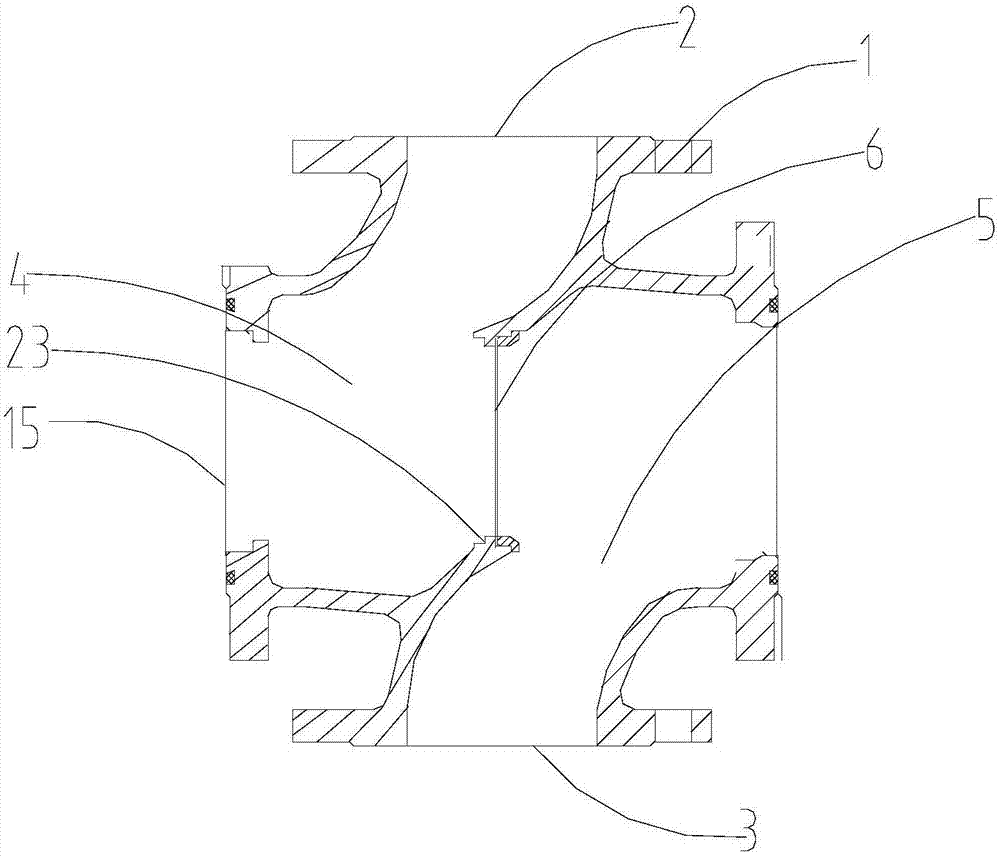
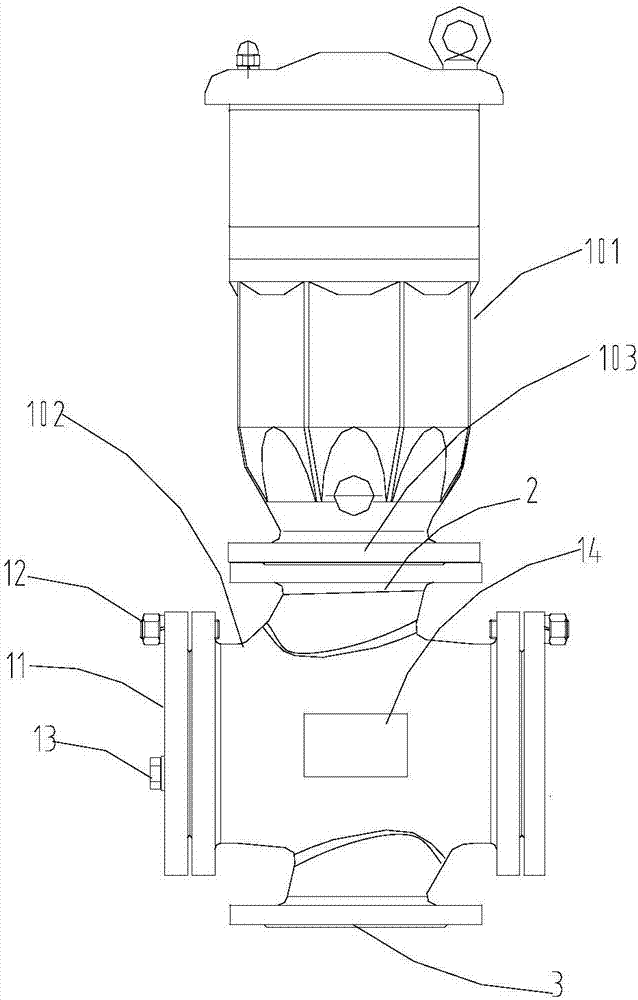
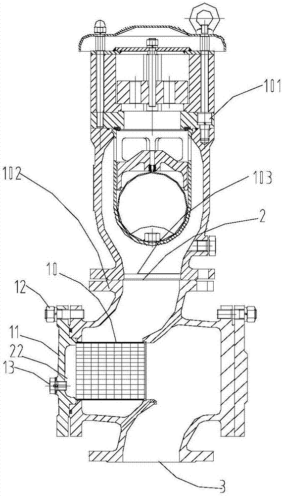
[0040] like Figure 1-8 As shown, the present embodiment provides a fast suction and slow discharge air valve with built-in filter, which is mainly used on pipelines with maintenance valves or shut-off valves, including the air valve main body 101 and the valve assembly 102, and the air valve main body 101 The valve opening 103 is connected to the valve assembly 102 through a flange seal, which is convenient for maintenance and replacement. The main body 101 of the air valve in this embodiment uses a water-proof air valve for further illustration. Specifically, the patent number 201520384037.9 applied by our company is used. The patent name is the anti-hammer air valve, and the specific structure and function will not be repeated one by one. This embodiment mainly integrates the air valve and the valve assembly without changing the structure of the air valve, and has the premise of having all the original functions of the air valve. Next, it has built-in filtration and quick s...

Embodiment 2

[0056] like Figure 9 As shown, this embodiment is basically the same as Embodiment 1, the difference is that the number of reinforcing ribs 21 is at least two, and the two reinforcing ribs 21 cross each other and are fixed on the port of the filter cartridge close to the valve cover in a cross shape. It can play the role of Embodiment 1, and can further strengthen the strength and stability of the filter cartridge with double-layer structure through a plurality of reinforcing ribs.


PUM


Abstract

The invention relates to the technical field of air valves and discloses a fast-sucking slow-discharging type air valve with a filtration function. The fast-sucking slow-discharging type air valve with the filtration function comprises an air valve main body and a valve assembly. A valve opening of the air valve main body is connected with the valve assembly. The valve assembly comprises a valve body. A valve body inner cavity is an S-shaped runner, and the valve body is divided into a left cavity and a right cavity. The two ends of the S-shaped runner are correspondingly provided with an airvalve main body connector and a pipeline connector which are not in the same cavity. A filter barrel is further arranged in the cavity provided with the air valve main body connector. The fast-suckingslow-discharging type air valve is suitable for being arranged in a pipeline provided with a service valve, a filter does not need to be arranged for the air valve independently, all original functions of the air valve are achieved, the air valve is provided with a filter, the runner in the valve assembly is in an S shape, resistance to water is large, resistance to air is small, air dischargingis facilitated, water draining is not facilitated, the ejection phenomenon of gas-liquid two-phase flow at the closing moment of the air valve can be reduced or avoided, and fast sucking and slow discharging functions of the air valve are enhanced.

Description

technical field [0001] The present invention relates to the technical field of air valves, and more specifically, relates to a fast-inhalation and slow-discharge air valve with self-filtering that integrates air valve functions, filter functions, and strengthens the air valve's fast suction and slow discharge. Background technique [0002] In long-distance water pipelines, the backlog of airflow in the pipeline will reduce the efficiency of pipeline water filling and even make it difficult to complete it smoothly. Therefore, high-speed intake and exhaust valves (air valves) need to be used to eliminate the airflow in the pipeline when filling the pipeline. However, the pipeline medium usually contains various impurities, especially in raw water conditions, leaves, aquatic weeds, various floating objects and wastes are very common. Once the impurities in the medium enter the air valve, the seal of the air valve will fail, causing the air valve to leak for a long time, which w...

Claims


Application Information

Patent Timeline
IPC IPC(8): F16K24/00F16K27/00F16K47/08B01D35/04
CPCB01D35/04F16K24/00F16K27/00F16K47/08
Inventor 黄靖桂新春罗建群谢爱华欧立涛
Owner 新疆珠华水工业科技有限公司
Learn More