Method for calibrating a temperature sensor present in an automation technology process

A technology of temperature sensor and automation technology, applied in the field of temperature measurement equipment, to achieve the effect of reliable on-site calibration

Active Publication Date: 2018-05-11
EHNDRESS KHAUZER GMBKH KO KG
View PDF9 Cites 0 Cited by
  • Summary
  • Abstract
  • Description
  • Claims
  • Application Information

AI Technical Summary

Problems solved by technology

As can be seen from the preceding description, known in-situ calibration solutions only work with specially manufactured temperature sensors

Method used


Image

  • Method for calibrating a temperature sensor present in an automation technology process
  • Method for calibrating a temperature sensor present in an automation technology process
  • Method for calibrating a temperature sensor present in an automation technology process

Examples


Embodiment Construction

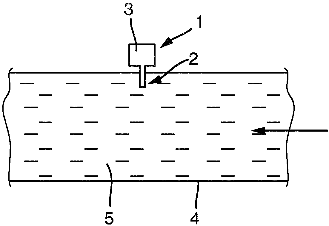
[0030] figure 1 is a schematic representation of an in situ calibratable temperature measuring device 1 of the present invention located in a process. In the case shown, the temperature measuring device 1 determines the temperature T of a medium 5 which flows through the line 4 in the direction of the arrow. The temperature measuring device 1 consists of a temperature sensor 2 (with a temperature sensitive element) and a control / evaluation unit 3 . While the temperature sensor 2 is in thermal contact with the medium 5, the control / evaluation unit 3 is arranged to be removed from the line 4 and thus from the actual process. Medium 5 is any fluid medium. Examples of temperature sensitive elements and corresponding temperature sensors 2 have been mentioned above but not exclusively. A large number of temperature measuring devices 1 are produced and sold by the applicant for use in a wide variety of automation technology applications. In general, known temperature sensors 2 ar...


PUM


Abstract

The invention relates to a method for calibrating a temperature sensor (1) present in an automation technology process, wherein the calibration method comprises the following method steps: providing or determining a temperature measuring range (DeltaT) to be passed through during the automation technology process; providing or determining a reference temperature (T ref ) occurring in the temperature measuring range (DeltaT); determining the temperature measurement value (T) by means of the temperature sensor (1); detecting whether the temperature measurement value (T) in the temperature measuring range (DeltaT) is at least approximately constant during predetermined time period (Deltat); correcting the at least approximately constant temperature measurement value (T) in the temperature measuring range (DeltaT) to the predetermined reference temperature (T ref ).

Description

technical field [0001] The invention relates to a method for calibrating a temperature sensor in an automation technology process. In-process calibration is also referred to as in-situ calibration. Furthermore, the invention relates to a temperature measuring device suitable for carrying out said calibration method. Background technique [0002] Temperature sensors are used in automation technology in a variety of applications. Applicant produces and sells a large number of different temperature sensors. Usually, the temperature sensor is fixed on the container wall (pipe, or pipe, wall, tank wall) in such a way that the temperature-sensitive part of the temperature sensor is in thermal contact with the medium located in the process, the temperature of which is to be measured or monitor. [0003] A fundamental problem for stable and reliable temperature measurement is temperature sensor drift. This drift means that the temperature sensor must be calibrated for a certain...

Claims


Application Information

Patent Timeline
IPC IPC(8): G01K15/00G01K13/02
CPCG01K7/02G01K7/16G01K13/02G01K15/005
Inventor 赫尔穆特·凯泰斯
Owner EHNDRESS KHAUZER GMBKH KO KG
Why Eureka
Try Eureka