Steady-state method thermal conductivity measurement experimental system and measurement method

A technology of thermal conductivity and measurement method, applied in the field of steady-state method thermal conductivity measurement experimental system, can solve the problems of affecting the accuracy of measurement, affecting the judgment of the balance state, cumbersome operation, etc., and reducing the effect of affecting the error.

Inactive Publication Date: 2018-03-13
CHINA UNIV OF PETROLEUM (EAST CHINA)
View PDF6 Cites 0 Cited by
  • Summary
  • Abstract
  • Description
  • Claims
  • Application Information

AI Technical Summary

Problems solved by technology

Due to the small temperature difference coefficient of metal materials and the influence of the external environment temperature, the measured electromotive force is often only a few millivolts, and the recorded data often fluctuates up and down, which affects the judgment of the equilibrium state, and then affects the accuracy of the measurement.
Also use platinum resistance (such as Pt100, Pt1000) to measure, use the property similar to the change of thermistor resistance with temperature, convert the resistance value into the corresponding temperature, so the calculated temperature error is relatively large; although its linearity is good , but its thermal response is slow
[0003] At present, a single thermocouple or Pt resistor is mostly used in measuring and experimental instruments. During operation, the sensor needs to be replaced between the heating plate and the cooling plate. The operation is cumbersome and easy to be affected by the environment. The limited sets of data measured by a single sensor cannot be accurately determined. Whether the system reaches a balanced state, the timing is basically measured by a stopwatch, the temperature is collected and recorded manually, and the heat dissipation rate is obtained by manual drawing method or step-by-step method, and the error of the final thermal conductivity is often too large

Method used


Image

  • Steady-state method thermal conductivity measurement experimental system and measurement method
  • Steady-state method thermal conductivity measurement experimental system and measurement method
  • Steady-state method thermal conductivity measurement experimental system and measurement method

Examples


Embodiment Construction

[0053] The present invention will be further described below in conjunction with the accompanying drawings and embodiments.

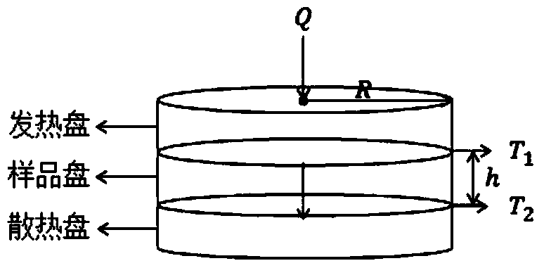
[0054] Such as figure 1 As shown, place the heating plate, the sample plate, and the cooling plate in close contact with each other coaxially from top to bottom.

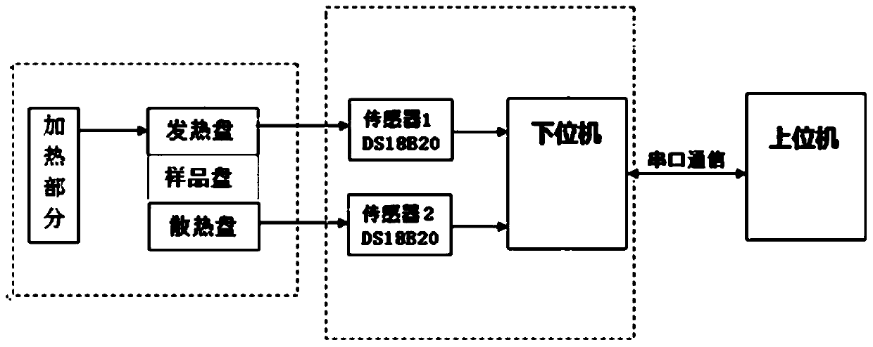
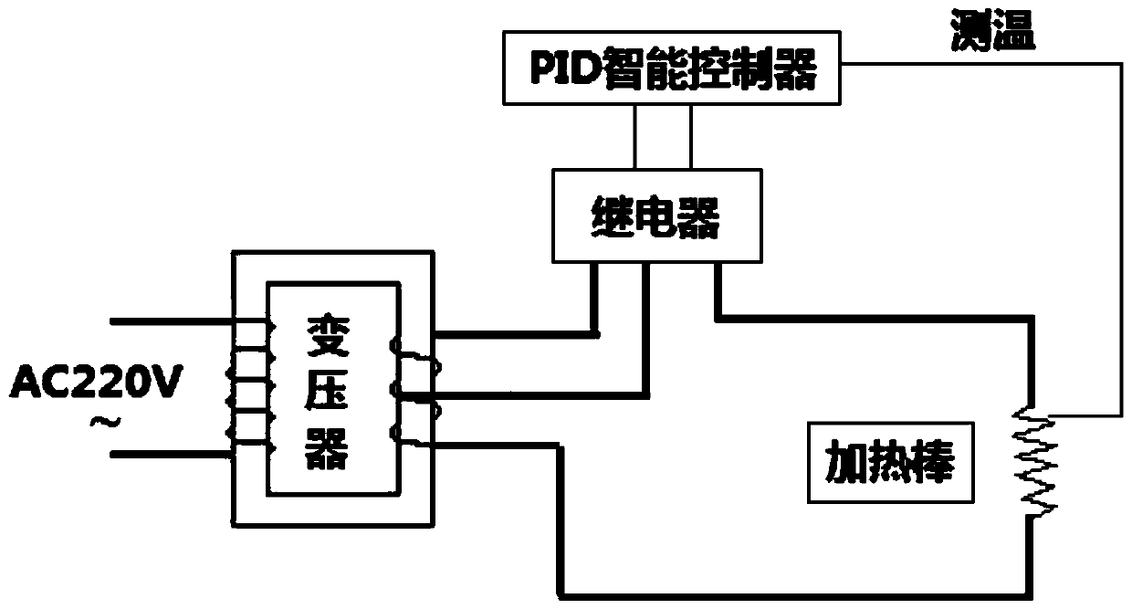
[0055] Such as figure 2 Shown is a block diagram of the entire measurement system. The heating part realizes the temperature-controlled heating of the heating plate, and the heat is transferred from the heating plate to the cooling plate through the sample plate to form a stable heat conduction process; two digital temperature sensors (DS18B20) are used to simultaneously collect the upper and lower (heating, heat dissipation) Disk) temperature, the temperature conversion delay time is only 750ms, and the sampling time interval can be set by software, and the collected temperature is processed by the single-chip microcomputer and sent to the host computer, and at the same time sent to the liq...


PUM

PropertyMeasurementUnit
thermal conductivityaaaaaaaaaa

Abstract

The invention discloses a steady-state thermal conductivity measurement experimental system and a measurement method; the system includes sequentially connected devices to be tested, a lower computer and a host computer; disk, a sample disk and a cooling disk, the heating disk is controlled and heated by a heating temperature control module; the heating disk is connected to the lower computer through the first temperature sensor, and the heat dissipation disk is connected to the lower computer through the second temperature sensor; the upper computer By sending a control command, the lower computer is notified to collect heat balance data or heat dissipation curve data of the device to be tested. Beneficial effects of the present invention: it has the advantage of effectively improving the precision and accuracy of measurement results.

Description

technical field [0001] The invention relates to a thermal conductivity measurement experimental system and a measurement method of a steady-state method. Background technique [0002] In the current measurement of thermal conductivity, a single thermocouple (such as copper-constantan, etc.) or a single Pt resistor is usually used for temperature measurement. When using a thermocouple to measure, it is first necessary to adjust the ice-water mixture (ie, the temperature reference). According to the thermoelectric effect of the metal material, when the two ends of the thermocouple are in contact with the ice-water mixture and the object to be measured, a thermoelectric potential can be formed. By measuring the thermoelectric potential , to achieve the purpose of measuring temperature. Due to the small temperature difference coefficient of metal materials and the influence of the external environment temperature, the measured electromotive force is often only a few millivolts,...

Claims


Application Information

Patent Timeline
Patent Type & Authority Patents(China)
IPC IPC(8): G01N25/20
CPCG01N25/20
Inventor 王龙苏玉亮李东霞姚远高原王彦娟梁桐启刘金玉
Owner CHINA UNIV OF PETROLEUM (EAST CHINA)
Why Eureka
Try Eureka