
Method for calibrating a temperature sensor located in an automation technology process

A technology of temperature sensor and automation technology, applied in the field of temperature measurement equipment, to achieve the effect of reliable on-site calibration

Active Publication Date: 2020-09-08
ENDRESS HAUSER INC
View PDF1 Cites 0 Cited by
  • Summary
  • Abstract
  • Description
  • Claims
  • Application Information

AI Technical Summary

Problems solved by technology

As can be seen from the preceding description, known in-situ calibration solutions only work with specially manufactured temperature sensors

Method used


Image

  • Method for calibrating a temperature sensor located in an automation technology process
  • Method for calibrating a temperature sensor located in an automation technology process
  • Method for calibrating a temperature sensor located in an automation technology process

Examples


Embodiment Construction

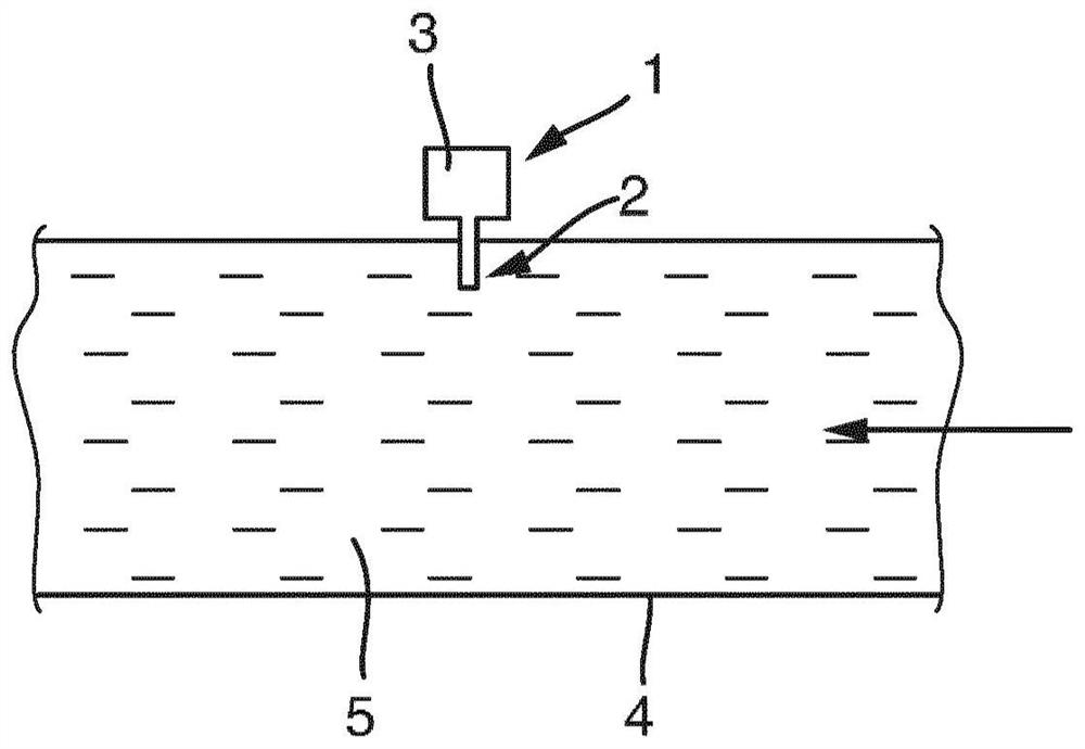
[0030] figure 1 It is a schematic representation of the in-situ calibratable temperature measuring device 1 of the present invention in the process. In the case shown, the temperature measuring device 1 determines the temperature T of the medium 5 which flows through the pipeline 4 in the direction of the arrow. The temperature measuring device 1 is composed of a temperature sensor 2 (with a temperature sensitive element) and a control / evaluation unit 3. While the temperature sensor 2 is in thermal contact with the medium 5, the control / evaluation unit 3 is arranged to be removed from the pipeline 4 and therefore from the actual process. Medium 5 is any fluid medium. Examples of temperature sensitive elements and corresponding temperature sensors 2 have been mentioned above non-exclusively. A large number of temperature measuring devices 1 are produced and sold by the applicant for use in diversified automation technology applications. Generally speaking, the known temperatu...


PUM


Abstract

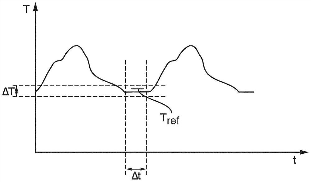
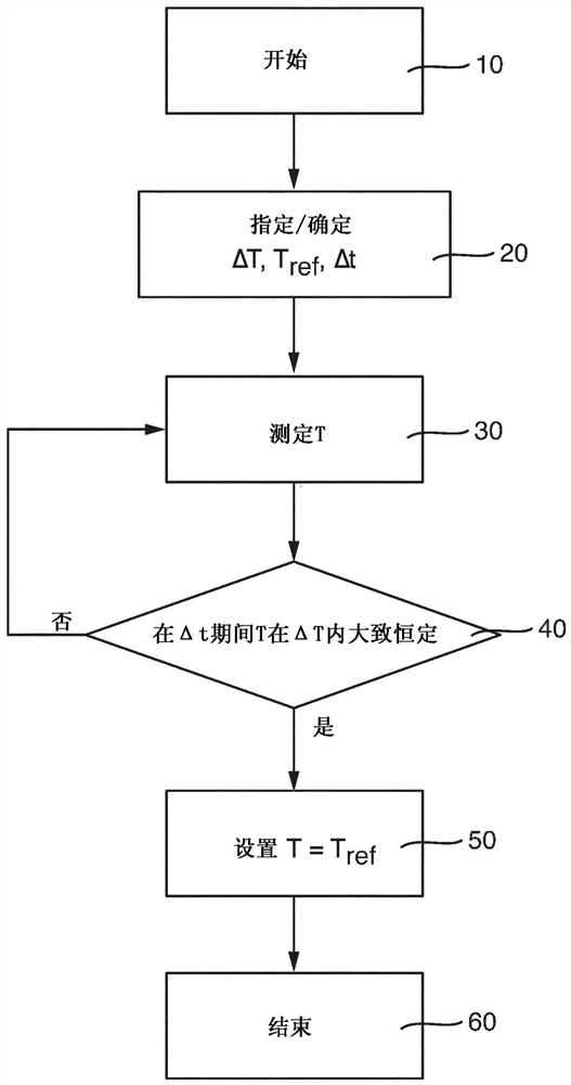
The application discloses a method for calibrating a temperature sensor located in a process of automation technology, wherein the calibration method comprises method steps as follows: specifying or ascertaining a temperature measuring range, which is passed through in the process of automation technology; specifying or ascertaining a reference temperature arising in the temperature measuring range; determining temperature measured values by means of the temperature sensor; detecting whether temperature measured values are at least approximately constant in the temperature measuring range during a specified time span; correcting the at least approximately constant, measured value of temperature in the temperature measuring range to the reference temperature.

Description

Technical field [0001] The invention relates to a method for calibrating a temperature sensor located in an automated technical process. In-process calibration is also called in-situ calibration. Furthermore, the invention relates to a temperature measuring device suitable for performing the calibration method. Background technique [0002] Temperature sensors are used in automation technology in diverse applications. The applicant produces and sells a large number of different temperature sensors. Usually, the temperature sensor is fixed on the container wall (pipe, pipe, wall, tank wall), in this way the temperature sensitive part of the temperature sensor is in thermal contact with the medium in the process, and the temperature of the medium will be measured or monitor. [0003] A basic problem for stable and reliable temperature measurement is drift of the temperature sensor. This drift means that the temperature sensor must be calibrated within a certain period of time. ...

Claims


Application Information

Patent Timeline
Patent Type & Authority Patents(China)
IPC IPC(8): G01K15/00G01K13/02
CPCG01K7/02G01K7/16G01K13/02G01K15/005
Inventor 赫尔穆特·凯泰斯
Owner ENDRESS HAUSER INC
Learn More