Wooden furniture plate machining device

A technology for sheet metal processing and wooden furniture, which is applied in the direction of manufacturing tools and workshop equipment, can solve problems such as inconvenient use, low production efficiency, and unclear shallow grooves, and achieve reduced production costs, accurate scribing accuracy, and improved scribing. The effect of line efficiency

Active Publication Date: 2018-05-15
启东盈乐门业有限公司
View PDF7 Cites 12 Cited by
  • Summary
  • Abstract
  • Description
  • Claims
  • Application Information

AI Technical Summary

Problems solved by technology

[0002] In the production process of non-metallic and non-plastic plate parts such as wood and bamboo, in order to fix the size of the cut, the method of marking the surface of the plate is often used to facilitate processing. Lines or sawing shallow grooves instead of scribing methods, and the method of manual scribing requires the operator to be precise when scribing and measuring, and errors are prone to occur during operation, and the operation process is slow and the production efficiency is low. The method of sawing shallow grooves instead of marking lines, the shallow grooves sawn out are often not clear due to the light, and in order to eliminate the original shallow grooves in the processing process, one more process needs to be carried out, which wastes the board and prolongs the working time. Inconvenient to use

Method used


Image

  • Wooden furniture plate machining device
  • Wooden furniture plate machining device
  • Wooden furniture plate machining device

Examples


Embodiment 1

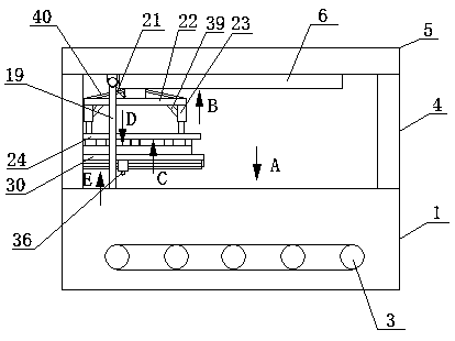
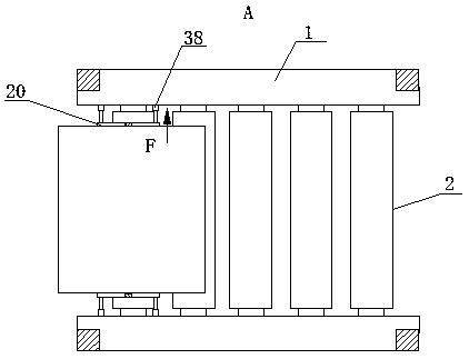
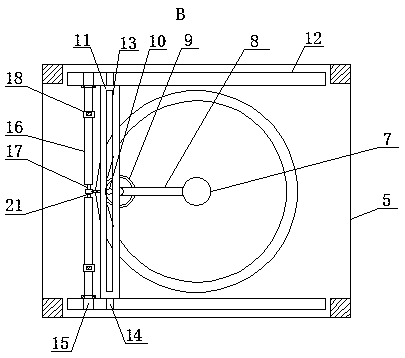
[0018] Embodiment 1: Place a plate with a width of 50mm on the roller 2, rotate the first screw rod 16 to make the two nuts 18 drive the vertical rod 19 to move relatively, and then drive the two fixed plates 20 to move relatively, so that the two fixed plates 20 Clamp the plate with a width of 50mm to prevent the plate from shaking in the marking line; when the second gear 28, the third gear 29 and the second ring gear 27 are in a static state, the second screw 31 and the roller 2 are perpendicular to each other state, the strip block 33 drives the marking pen 36 to move left and right, and then the marking operation is performed on the plate.

Embodiment 2

[0019] Embodiment 2: Place a plate with a width of 70mm on the roller 2, rotate the first screw rod 16 to make the two nuts 18 move relative to each other, and the nut 18 and the fixed plate 20 are fixedly connected by a vertical rod 19, which can drive two The fixed plates 20 move relative to each other, so that the two fixed plates 20 clamp the plate with a width of 70 mm to prevent the plate from shaking during the marking process; the second gear 28 and the third gear 29 rotate to drive the second ring gear 27 to rotate, and the second gear 28 and the third gear 29 rotate to drive the second ring gear 27 to rotate. The second ring gear 27 is fixedly connected with the third connecting plate 30, so that the third connecting plate 30 can be rotated, and then the second screw rod 31 and the roller 2 can be in a state parallel to each other, and then the second screw rod 31 rotates to make the strip block 33 drive The scribing pen 36 moves back and forth to perform a scribing o...


PUM


Abstract

A wooden furniture plate machining device comprises a front fixed seat and a rear fixed seat. Multiple horizontal roller wheels are movably mounted between the two fixed seats. Chain wheels are fixedly mounted at the front end and the rear end of a rotary shaft of each roller wheel. The chain wheels are located on the outer sides of the fixed seats. The multiple chain wheels located on the outer side of the same fixed seat are movably connected through a chain. Vertical supporting rods are fixedly mounted on the two sides of the top face of each fixed seat correspondingly. The top ends of thefour supporting rods are fixedly connected through a horizontal supporting plate. Guide grooves with sections in dovetail shapes are formed in the front end and the rear end of the bottom face of thesupporting plate correspondingly. A guide block is arranged in each guide groove. Nuts are fixedly connected with vertical rods, then first screws rotate, the two vertical rods can oppositely move ormove in the reverse directions, and therefore adjustment can be carried out according to different plate widths, and the use requirements of the different plate widths can be met. A plate is fixed through two fixing plates, the plate can be prevented from moving in the lineation process, and inaccurate lineation is avoided.

Description

technical field [0001] The invention relates to a furniture board processing device, in particular to a wooden furniture board processing device. Background technique [0002] In the production process of non-metallic and non-plastic plate parts such as wood and bamboo, in order to fix the size of the cut, the method of marking the surface of the plate is often used to facilitate processing. Lines or sawing shallow grooves instead of scribing methods, and the method of manual scribing requires the operator to be precise when scribing and measuring, and errors are prone to occur during operation, and the operation process is slow and the production efficiency is low. The method of sawing shallow grooves instead of marking lines, the shallow grooves sawn out are often not clear due to the light, and in order to eliminate the original shallow grooves in the processing process, one more process needs to be carried out, which wastes the board and prolongs the working time. It is...

Claims


Application Information

Patent Timeline
Patent Type & Authority Applications(China)
IPC IPC(8): B25H7/04
Inventor 邱尚周
Owner 启东盈乐门业有限公司
Why Eureka
Try Eureka