High-strength transparent hydraulic coupling device for PIV testing

A technology of transparent liquid and coupler, which is applied in the direction of transmission, fluid transmission, transmission control, etc., can solve the problems of inconvenient placement of instruments, unclear images, etc., and achieve simple and flexible design, avoid light scattering, and facilitate observed effect

Active Publication Date: 2018-05-15
JILIN UNIV
View PDF10 Cites 4 Cited by
  • Summary
  • Abstract
  • Description
  • Claims
  • Application Information

AI Technical Summary

Problems solved by technology

[0005] What the present invention aims to solve is that the image obtained by PIV test is not clear, and the problem of inconvenient placement of the instrument when the internal flow field of the pump wheel and the turbine is measured separately

Method used


Image

  • High-strength transparent hydraulic coupling device for PIV testing
  • High-strength transparent hydraulic coupling device for PIV testing
  • High-strength transparent hydraulic coupling device for PIV testing

Examples


Embodiment Construction

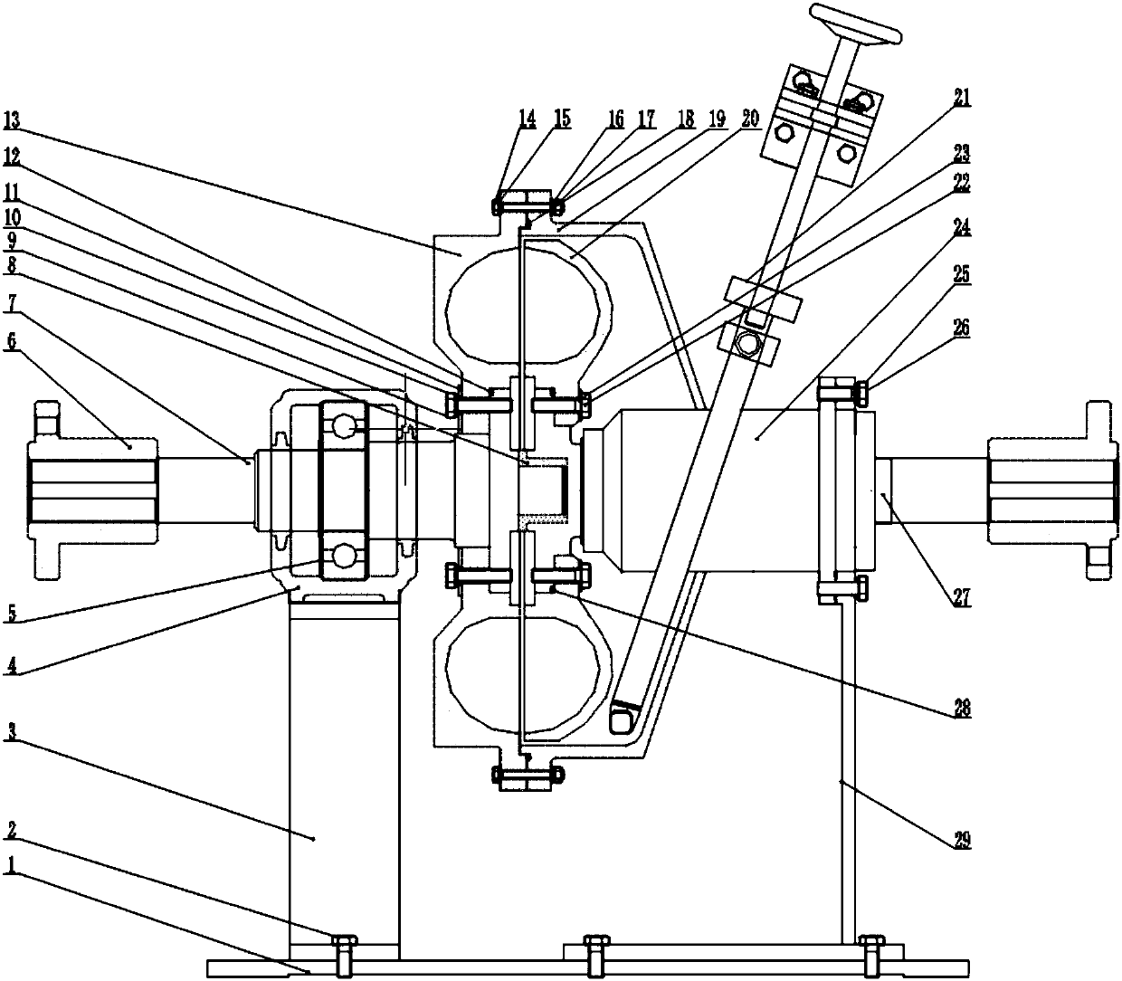
[0024] The present invention is described in detail below in conjunction with accompanying drawing:

[0025]A high-strength transparent hydraulic coupling device for PIV testing, the device includes a mounting base plate 1, a vertical bearing support bracket 3 is fixed on the mounting base plate 1 through No. 1 hex head bolts 2, and the input end of the input shaft 7 passes through Coupling 6 is connected with the starter motor, the edge of the outer ring of deep groove ball bearing 5 is stuck in the groove of the inner edge of bearing seat 4 on bearing seat bracket 3, and deep groove ball bearing 5 is transitionally fitted with input shaft 7, so that the input shaft 7 Supported on the bearing housing 4, the outer wall of the pump wheel 13 is processed into a plane along the radial direction of the pump wheel 13 and a cylindrical surface along the axial direction of the pump wheel 13, and the angle between the joint of the plane and the cylindrical surface It is 90 degrees to ...


PUM


Abstract

The invention provides a high-strength transparent variable speed hydraulic coupling device for PIV testing. The cavity shells of the pump wheels are processed into two planes perpendicular to the radial and axial direction of the pump wheels. The scattering of light is avoided, and the centers of turbine housings are not closed. A circulating water system is adopted to achieve the purpose of water circular flow. A way of symmetric machining is adopted in the structure of a shaft, the external shape of an input shaft and an output shaft is exactly same with each other, and a camera is convenient to symmetrically install. Input and output are reversed to achieve the testing of the turbine side flow field. The expansion and shrink of a spoon pipe are used to change the filling volume of a working cavity so as to adjust the output torque of a coupling, and the purpose of speed regulation is achieved. The pump wheels, the turbines and the turbine housings are made of transparent organic glass material and convenient to observe. Pump wheel blades and turbine blades are black to avoid the scattering of light. The structure of the input shaft and the output shaft is simple and flexible indesign, the input and the output can be switched flexibly, and the situation of the flow field of the pump wheels and the turbine is convenient to measure.

Description

technical field [0001] 本发明涉及一种满足PIV测试用的高强度透明液力偶合器装置,该装置采用输入轴和输出轴对称布置的方式,并优化了腔体外形,可以灵活、清晰、抗干扰的实现泵轮和涡轮内部流场的测量。 Background technique [0002] 大功率液力偶合器传动装置是大型火电 / 核电站中锅炉给水泵的重要调速节能装备,随着发电机组容量的不断增加,液力偶合器输入的转速和功率大幅度提高,其内部流动状态 不再符合流动相似条件,额定工况下的原始特性参数发生改变且难以预测,导致其能容下降、效率降低、输出特性失稳及系统振动加剧等一系列问题,严重威胁了发电机组的安全 Stable operation. 因此,开展大功率液力偶合器气液两相瞬态流场方面的研究十分迫切,亟需发展有效的相关研究理论和方法。 [0003] 随着计算机技术和计算流体动力学(CFD)的发展,在液力传动元件数值模拟测试方面,许多学者和技术人员开展了大量的研究工作,特别是由于液力偶合器内部气液两相流动的复杂性,很难用数学模型对其进行准确的描述,所以需要对内部流场进行可视化研究。PIV是一种先进的无扰、瞬态、全流场速度测量的流动可视化方法,不仅能够显示流体流动的物理形态,而且能够提供瞬时全场流动的定量信息。目前对于液力传动元件的流场测试模型多采用封闭腔型,由于缺少外循环的充排液系统,在测试过程中流动介质发热严重,影响测试工作的进行。同时被测试叶轮外壳形状一般呈曲面形式,当激光照射到曲面上散射现象比较严重,从而影响示踪粒子的轨迹识别,导致部分流场信息的缺失,甚至是流场可视化试验失败。目前测试用的液力传动元件模型针对于中小型液力偶合器,存在强度低、刚度不足、透明度有限,无法满足高转速、大功率液力偶合器流场测试要求。 [0004] CN203414271U公开了“液力偶合器检测装置”,该专利主要讨论了应用于测试偶合器的泄露情况及工作参数的一种检测装置,以判断偶合器工作是否正常。 Contents of the invention [0005] 本发明所要解决的是PIV测试所得的图像不清晰、泵轮与涡轮内部流场分开测量时仪器摆放位置上的不便的问题。 figure 1 是本发明——PIV测试用高强度透明液力偶合器装置的结构示意图 [0006] The...

Claims


Application Information

Patent Timeline
Patent Type & Authority Applications(China)
IPC IPC(8): F16H41/04F16H41/24F16H61/64G01M13/02
CPCF16H41/04F16H41/24F16H61/64G01M13/02
Inventor 卢秀泉马文星柴亚龙张剑楠胡春玉
Owner JILIN UNIV
Why Eureka
Try Eureka