Connecting-rod type movement structure auxiliary vehicle handle

A motion structure, link-type technology, used in bicycle accessories, bicycle brakes, etc., can solve problems such as unreasonable and inconvenient holding, and achieve the effect of convenient and labor-saving holding.

Inactive Publication Date: 2018-05-22
广州市腾昶贸易有限公司
View PDF6 Cites 2 Cited by
  • Summary
  • Abstract
  • Description
  • Claims
  • Application Information

AI Technical Summary

Problems solved by technology

[0002] In the natural state, when the hand holds something, the natural state of the four fingers should be the same movement distance. However, the current operation structure of the auxiliary handle of bicycles, motorcycles and other riding vehicles has only one center of rotation, which is close to the center of rotation. The position closer to the handlebar and farther from the center of rotation is farther away from the handlebar, that is, the index finger is closest to the auxiliary handlebar, and the little finger is farthest from the auxiliary handlebar, which makes it inconvenient to hold. Moreover, when holding the auxiliary handlebar for brake, The auxiliary handle will rotate around the center of rotation. During this process, the stroke of the index finger is the shortest, while the stroke of the little finger is the longest. This design is not ergonomically reasonable

Method used


Image

  • Connecting-rod type movement structure auxiliary vehicle handle
  • Connecting-rod type movement structure auxiliary vehicle handle
  • Connecting-rod type movement structure auxiliary vehicle handle

Examples


Embodiment Construction

[0016] In order to make the object, technical solution and advantages of the present invention clearer, the present invention will be further described in detail below in conjunction with the accompanying drawings and embodiments. It should be understood that the specific embodiments described here are only used to explain the present invention, not to limit the present invention.

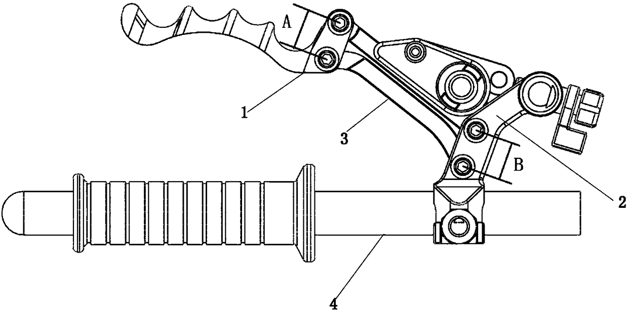
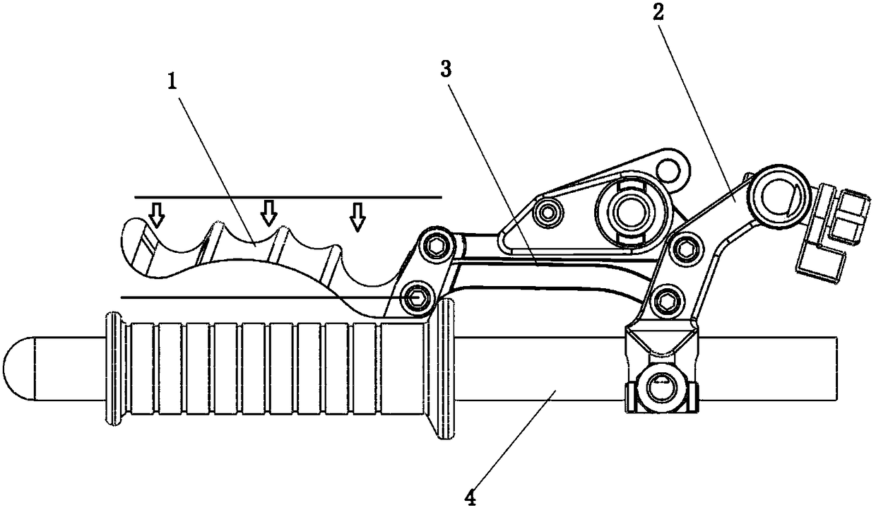
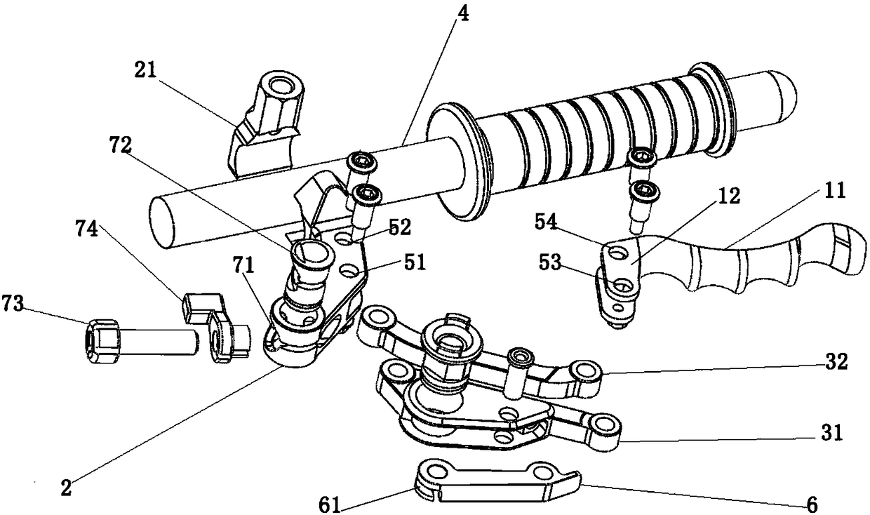
[0017] Such as Figure 1-3 As shown, the auxiliary handle of a vehicle with a link type movement structure includes an auxiliary handle 1, a mounting frame 2 and a connecting rod assembly 3. The auxiliary handle 1 includes a grip part 11 and a connecting frame 12, and the grip part 11 is roughly the same as the handlebar 4. Parallel, the base of the mounting frame 2 is fixedly installed on the handlebar 4 through the mounting base 21, and a pair of hinged holes are respectively provided on the mounting frame 2 and the connecting frame 12, which are respectively hinged holes 51, hinged holes 52, hin...


PUM


Abstract

The invention relates to the technical field of auxiliary handle movement structures, in particular to a connecting-rod type movement structure auxiliary vehicle handle. The handle comprises an auxiliary handle body, a mounting frame and a connecting-rod assembly; the auxiliary handle body comprises a holding part and a connecting frame; a base part of the mounting frame is fixedly mounted on a handlebar through a mounting base, the mounting frame and the connecting frame are provided with two pairs of hinge holes with the same spacing distance respectively, the connecting-rod assembly comprises a first connecting rod and a second connecting rod which are arranged in parallel, the two ends of the first connecting rod are hinged to two hinge holes in the mounting frame and the connecting frame respectively, the two ends of the second connecting rod are hinged to the hinged holes in the other sides of the mounting frame and the connecting frame respectively, the distance between the twohinge portions of the first connecting rod is equal to that between the two hinge portions of the second connecting rod, and the connecting frame, the first connecting rod, the mounting frame and thesecond connecting rod are sequentially hinged to form a parallelogram movement structure; through the design of the parallelogram movement structure, the auxiliary handle is always kept parallel to the handlebar in the holding process, the holding operation is more convenient and saves labor, and the auxiliary vehicle handle better accords with ergonomic design.

Description

technical field [0001] The invention relates to the technical field of the movement structure of the auxiliary handle, in particular to the auxiliary handle of a vehicle with a link type movement structure. Background technique [0002] In the natural state, when the hand holds something, the natural state of the four fingers should be the same movement distance. However, the current operation structure of the auxiliary handle of bicycles, motorcycles and other riding vehicles has only one center of rotation, which is close to the center of rotation. The position closer to the handlebar and farther from the center of rotation is farther away from the handlebar, that is, the index finger is closest to the auxiliary handlebar, and the little finger is farthest from the auxiliary handlebar, which makes it inconvenient to hold. Moreover, when holding the auxiliary handlebar for brake, The auxiliary handle will rotate around the center of rotation. During this process, the stroke...

Claims


Application Information

Patent Timeline
Patent Type & Authority Applications(China)
IPC IPC(8): B62L3/02
CPCB62L3/026
Inventor 陈仙富
Owner 广州市腾昶贸易有限公司
Why Eureka
Try Eureka