Device for inserting computer memory bank into slot

A technology of memory sticks and computers, which is applied in the field of computer equipment, can solve problems such as inability to adapt to large-scale production, high labor intensity of the operator, and heavy force on fingers, and achieve compact structure, avoid local deformation and damage, and compact and light structure Effect

Inactive Publication Date: 2017-10-20
ZHENGZHOU YUNHAI INFORMATION TECH CO LTD
View PDF9 Cites 1 Cited by
  • Summary
  • Abstract
  • Description
  • Claims
  • Application Information

AI Technical Summary

Problems solved by technology

[0002] Memory sticks are an essential component of products such as computer servers and storage. In the prior art, when installing a memory stick into a slot, you usually use your fingers to press the outer edge of the memory stick and press the memory stick into the memory slot. , the defect of this operation method is that because the fingers need to press down the memory stick hard, the fingers are under a lot of force, and the fingers will feel pain after working for a period of time, especially when there is a lot of memory and it takes a long time to install and operate. The labor intensity of the operator is high, and the fingers are swollen and painful, and even worn out and bleed, which brings harm to the operator, and the work efficiency is low, which cannot meet the needs of large-scale production.

Method used


Image

  • Device for inserting computer memory bank into slot
  • Device for inserting computer memory bank into slot
  • Device for inserting computer memory bank into slot

Examples


Embodiment 2

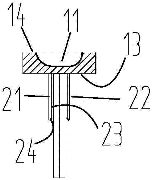
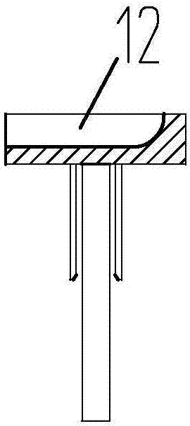
[0033] combine image 3 , the groove 11 is an open groove 12 provided with an opening at a mating position close to the back of the finger pulp. The open slot is easy to process and has a large force application area, which is more suitable for the use of memory sticks that require greater pressing force to operate. Other with reference to embodiment 1. I won't repeat them here.

Embodiment 3

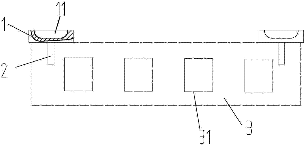
[0035] combine Figure 4 and Figure 5 , the pressing plate 1 and the positioning block 2 are respectively provided with two, and the two pressing plates are connected by an intermediate connecting plate 4 . Described intermediate connecting plate 4 comprises connecting plate one 41, connecting plate two 42, and one end of connecting plate one 41, connecting plate two 42 is connected by connecting sleeve 5 in the middle, and the other end of connecting plate one 41 is connected with a pressing plate, connects The second plate 42 is connected with another pressing plate, and the distance and position between the first connecting plate 41 and the second connecting plate 42 are adjusted through the connecting sleeve. The first connecting plate 41 and the second connecting plate 42 adopt a cylindrical structure, and are respectively connected to the connecting sleeve through screw fit 5 . Can adopt connecting sleeve to be internal thread 51, connecting plate one 41, connecting p...

Embodiment 4

[0037] combine Figure 4 , the outer position of a pressing plate at one end is connected with a limit block 6, the limit block is matched with the end face of the main board, and the positioning of the pressing plate in the length direction of the memory bar is realized through the end face of the main board. Through the limit and positioning function of the end face of the main board, the consistency and accuracy of the matching position between the pressing board and the memory stick can be realized, and the operator can avoid the deviation and uncertainty of the position of the pressing board and the memory stick when the operator manually operates the pressing board. Changes in the matching position will damage the memory stick and unknown components on the memory stick. For other references to Embodiment 3, details are not repeated here.


PUM


Abstract

The invention discloses a device for inserting a computer memory stick into a slot, which comprises a pressing plate and a positioning block. The end faces are connected, the inner end face of the pressing plate is matched with the upper end of the memory bar, the inner end faces of the positioning plate 1 and the positioning plate 2 are planes, the inner end faces of the positioning plate 1 and the positioning plate 2 are arranged in parallel, and the inner end faces of the two inner end faces The distance between them matches the width of the memory stick. The present invention is compact in structure, light in weight, convenient to hold and labor-saving, reduces the labor intensity of the operator, and improves the work efficiency of the operator.

Description

technical field [0001] The invention relates to the technical field of computer equipment, in particular to a device for inserting a computer memory stick into a slot. Background technique [0002] Memory sticks are an essential component of products such as computer servers and storage. In the prior art, when installing a memory stick into a slot, you usually use your fingers to press the outer edge of the memory stick and press the memory stick into the memory slot. , the defect of this operation method is that because the fingers need to press down the memory stick hard, the fingers are under a lot of force, and the fingers will feel pain after working for a period of time, especially when there is a lot of memory and it takes a long time to install and operate. The labor intensity of the operator is high, and the fingers are swollen and painful, and may even be worn out and bleed, which brings harm to the operator, and the work efficiency is low, which cannot meet the ne...

Claims


Application Information

Patent Timeline
Patent Type & Authority Applications(China)
IPC IPC(8): B25B27/02
CPCB25B27/02
Inventor 宋慧敏
Owner ZHENGZHOU YUNHAI INFORMATION TECH CO LTD
Why Eureka
Try Eureka