
Tire wear resistance and wheel impact resistance test device

A test device and wear resistance technology, which is applied in the field of tire manufacturing, can solve the problems of potential safety hazards, the inability to simulate tire friction, impact, impact, etc., and achieve the effect of accurate impact resistance

Active Publication Date: 2020-10-09
陈高强
View PDF7 Cites 0 Cited by
  • Summary
  • Abstract
  • Description
  • Claims
  • Application Information

AI Technical Summary

Problems solved by technology

With the development of automobiles in the direction of high speed, safety, energy saving, and comfort, the requirements for high performance tires are also increasing year by year. The wear resistance of tires has become an important indicator for testing the quality of tires. At the same time, some roads are now in Speed ​​bumps will be set up where speed limits are required. When the car passes through the speed bumps, it will cause a large impact on the wheel hub of the tire and cause cracks, which will bring safety hazards. Therefore, after the tires are produced, it is necessary to sample the tires. Test the wear resistance of tires and the impact resistance of wheels
[0003] Traditional devices for testing tire wear resistance and wheel hub impact resistance can only simply test tires and wheel hubs, and cannot simulate the friction and impact of tires in complex road conditions in real life

Method used


Image

  • Tire wear resistance and wheel impact resistance test device
  • Tire wear resistance and wheel impact resistance test device
  • Tire wear resistance and wheel impact resistance test device

Examples


Embodiment Construction

[0025] The implementation of the present invention will be described in detail below with reference to the drawings and examples, so as to fully understand and implement the implementation process of how to use technical means to solve technical problems and achieve technical effects in the present invention.

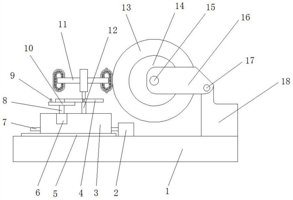
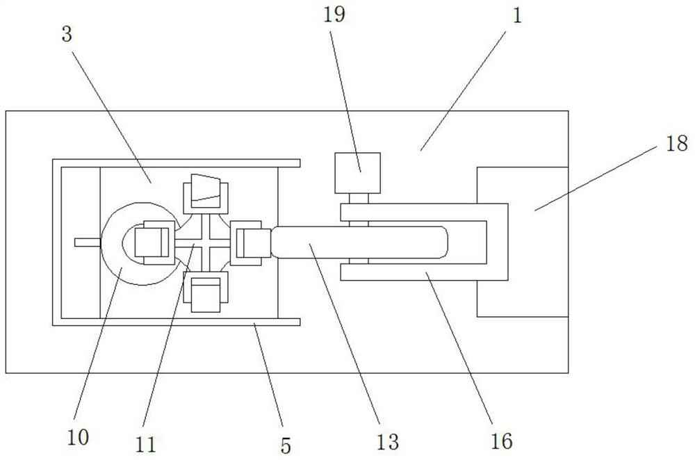
[0026] The present invention will be further described below in conjunction with accompanying drawing and specific embodiment, as Figure 1 to Figure 9 Shown: comprise detection platform 1, the first motor 19 and tire fixing device, the first motor 19 is arranged on the tire fixing device, it is characterized in that: one end of the upper end face of detection platform 1 is provided with mount 18, and tire fixing device is arranged on The upper end face of mounting base 18, the other end of detection platform 1 upper end face is provided with slide rail 5, is provided with the slide table 3 that its shape matches in the slide rail 5, slide table 3 middle part is connecte...


PUM


Abstract

The invention discloses a testing device for tire wear resistance and hub impact resistance. The testing device for the tire wear resistance and hub impact resistance comprises a testing table, a first motor and a tire fixing device, wherein a sliding table is arranged at one end of the testing table, a second rotating shaft is arranged on the sliding table, a cross bracket is arranged at one end,far away from the sliding table, of the second rotating shaft, an impact friction device, an inclined friction device, a pit friction device and a flat land friction device are arranged on the crossbracket, the impact friction device comprises a circular rotating belt I, a rolling seat I, a rolling body I and a cage I for keeping the position of the rolling body I, the rolling body I and the cage I are arranged between the circular rotating belt I and the rolling seat I, the outer surface of the circular rotating belt I is a rough surface, and impact blocks are arranged on the outer surfaceof the circular rotating belt I. The testing device for the tire wear resistance and hub impact resistance disclosed by the invention can more accurately simulate the friction suffered by a tire and impact suffered by a hub under complex road conditions or single road conditions, thereby more accurately detecting the wear resistance of the tire and the impact resistance of the hub.

Description

technical field [0001] The invention relates to the field of tire manufacturing, in particular to a test device for tire wear resistance and hub impact resistance. Background technique [0002] Tires are one of the most important components of a car. Its main function is to support the entire weight of the vehicle, bear the load of the car, transmit traction and braking torque, and ensure the adhesion between the wheel and the road. Most of the tires are rubber material. With the development of automobiles in the direction of high speed, safety, energy saving, and comfort, the requirements for high performance tires are also increasing year by year. The wear resistance of tires has become an important indicator for testing the quality of tires. At the same time, some roads are now in Speed ​​bumps will be set up where the speed limit is required. When the car passes through the speed bump, it will cause a large impact on the wheel hub of the tire and cause cracks, which wil...

Claims


Application Information

Patent Timeline
Patent Type & Authority Patents(China)
IPC IPC(8): G01N3/56G01M7/08G01M17/013
CPCG01M7/08G01M17/013G01N3/56
Inventor 陈高强
Owner 陈高强
Learn More