Fixing device for plug power-on

A technology for fixing devices and plugs, which is applied to the parts of connecting devices, coupling devices, circuits, etc., which can solve the problems of complicated disassembly of plugs, etc., and achieve the effects of convenient use, avoiding power connection, and simple installation and use

Active Publication Date: 2018-05-25
WENZHOU TECELLENT MACHINERY CO LTD
View PDF6 Cites 2 Cited by
  • Summary
  • Abstract
  • Description
  • Claims
  • Application Information

AI Technical Summary

Problems solved by technology

But the operation of removing the plug of this device is too cumbersome

Method used


Image

  • Fixing device for plug power-on
  • Fixing device for plug power-on
  • Fixing device for plug power-on

Examples


specific Embodiment approach 1

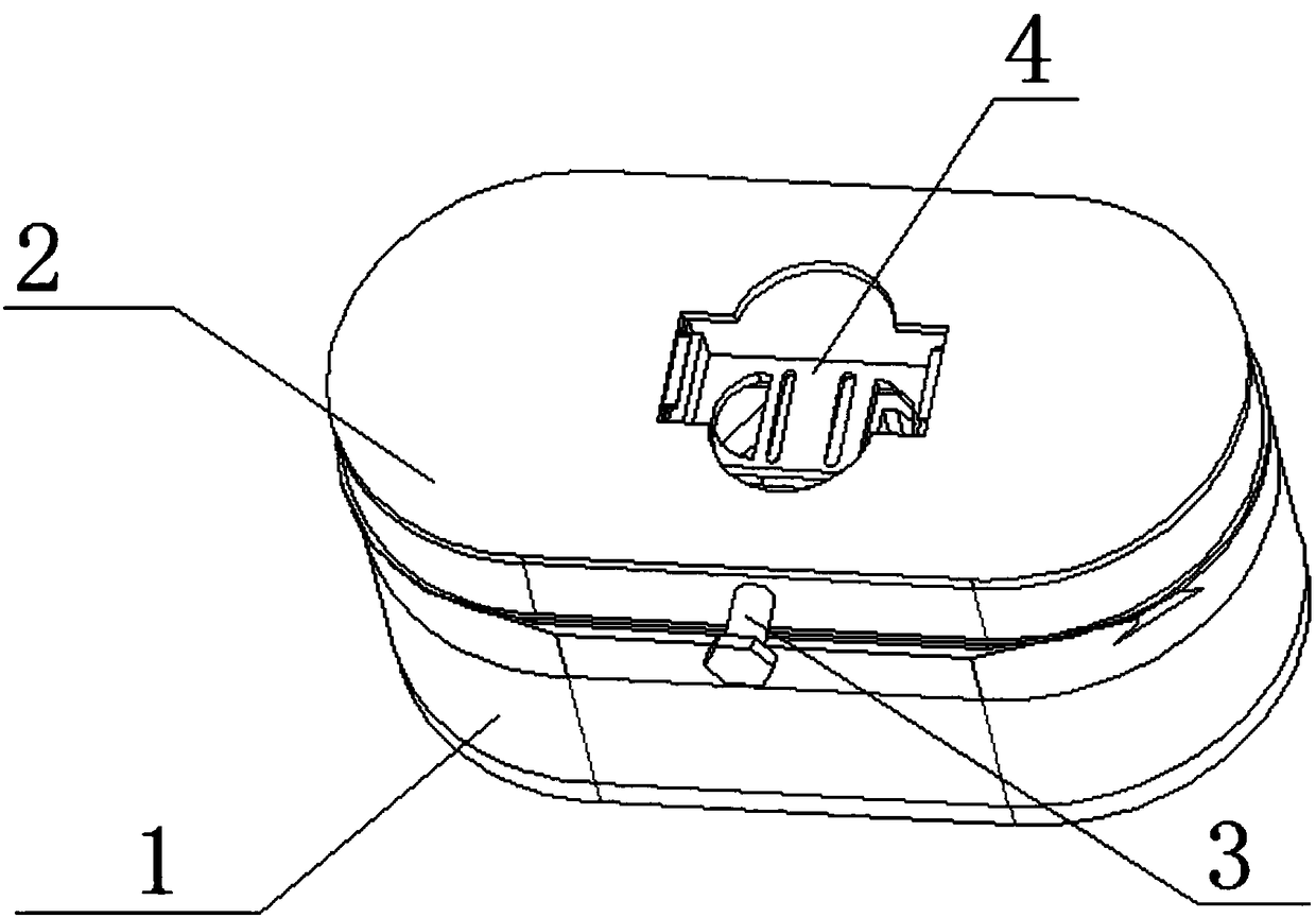
[0032] Such as Figure 1 to Figure 10 As shown, a fixing device for connecting plugs to electricity, including a socket 1, a fixing device housing 2, a fixing device control structure 3 and a fixing device carrier structure 4, the fixing device housing 2 is slidably connected to the socket 1 , the fixing device control structure 3 is rotatably connected in the fixing device housing 2 , the fixing device control structure 3 is linked with the fixing device carrier structure 4 , and the fixing device carrier structure 4 is fixedly connected in the fixing device housing 2 . It is possible to manually push the plug into the carrier structure 4 of the fixing device, push the plug to fit the carrier structure 4 of the fixing device to the socket 1, and push the rotation of the fixing device control structure 3 at the same time, when the plug is inserted into the socket 1 , the rear end of the plug is blocked by the fixing device control structure 3 to realize the fixing of the plug,...

specific Embodiment approach 2

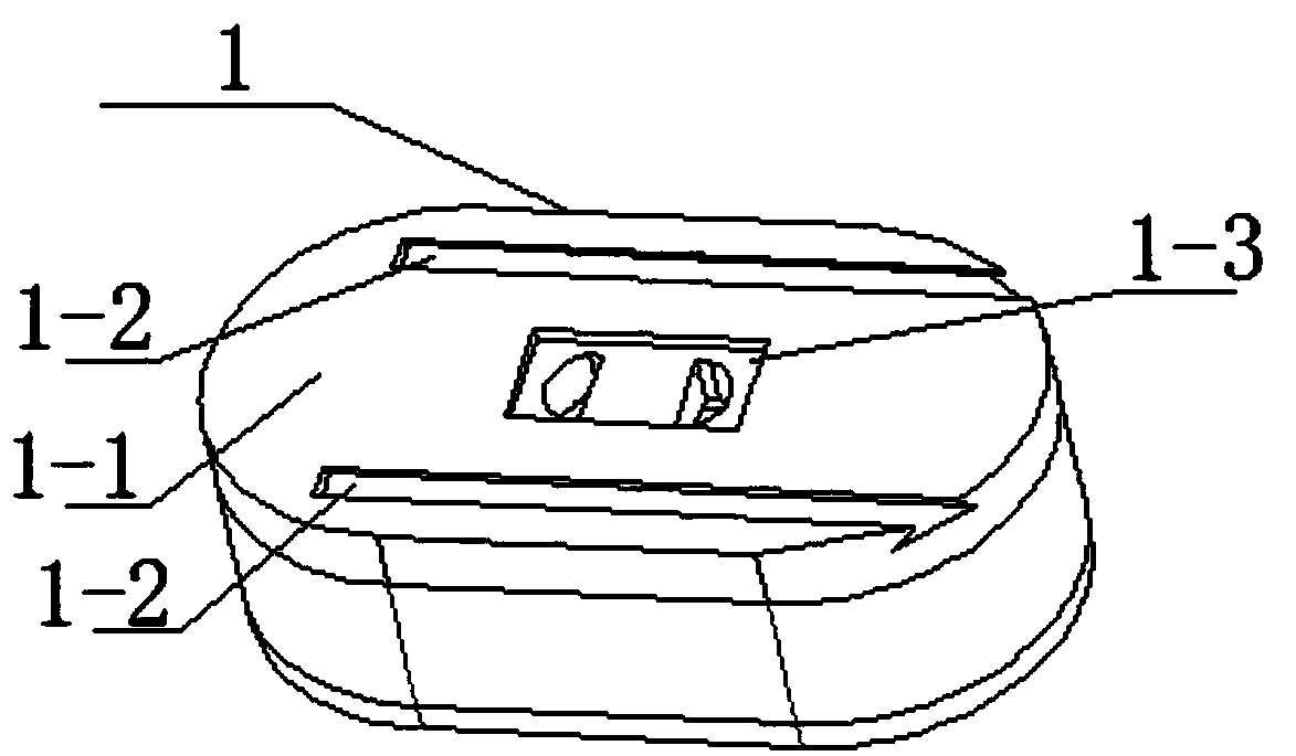
[0033] Such as Figure 1 to Figure 10 As shown, this embodiment further explains the first embodiment, the socket 1 includes a socket 1-1, a T-shaped groove 1-2 and a rectangular groove 1-3, and the upper end of the socket 1-1 is provided with two communicating There are two T-shaped slots 1-2 for the power socket inside the socket 1-1, the two T-shaped slots 1-2 are arranged on the upper end of the socket 1-1, and the rectangular groove 1-3 is arranged on the socket 1-1. 1 at the two power sockets.

specific Embodiment approach 3

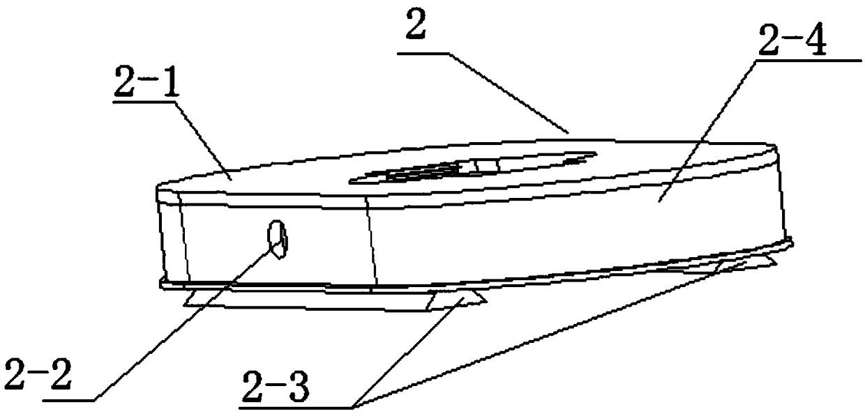
[0034] Such as Figure 1 to Figure 10As shown, this embodiment further describes the second embodiment, the fixing device housing 2 includes an upper end cover 2-1, a control round hole 2-2, a T-shaped convex edge 2-3 and a housing 2-4, The upper end cover 2-1 is fixedly connected to the upper end of the housing 2-4, the control round hole 2-2 is arranged at the rear end of the housing 2-4, the control round hole 2-2 communicates with the inside of the housing 2-4, and the T-shaped convex There are two along the 2-3, and the two T-shaped convex edges 2-3 are respectively slidingly connected in the two T-shaped slots 1-2, and the lower end of the housing 2-4 is provided with a connecting rectangular slot, and the connecting rectangular slot is connected to the rectangular Groove 1-3;

[0035] The upper end cover 2-1 includes an upper end plate 2-1-1, a plug port 2-1-2, a rack baffle chute 2-1-3 and a gear rectangular hole 2-1-4, and an upper end plate 2-1-2. 1-1 is fixedly co...


PUM


Abstract

The invention relates to the field of power distributor connectors, in particular to a fixing device for plug power-on. The device comprises a power distributor base, a fixing device shell, a fixing device control structure and a fixing device carrier structure. The fixing device shell is slidingly connected to the power distributor base, the fixing device control structure is rotatably connectedin the fixing device shell, the fixing device control structure is in linkage with the fixing device carrier structure, and the fixing device carrier structure is fixedly connected in the fixing device shell. The fixing device for plug power-on has the advantages that the fixing device and a power distributor can be manually disassembled, the device is extremely easy to install and use, a plug canbe fixed by the device during plug power-on at the same time, and the device is convenient to use; meanwhile, the plug does not need to be unplugged by hands in the process of unplugging the plug, byrotating a hand rotation block, the plug can be automatically ejected, and the situation is avoided that electric shock is caused when the wet hand unplugs the plug.

Description

technical field [0001] The invention relates to the field of plug connectors, in particular to a fixing device for connecting plugs to electricity. Background technique [0002] In the process of using the plug to connect electricity in daily life, it often happens that the plug socket is loose due to the long-term use of the plug-in strip, and the plug is prone to fall off. Patent No. CN201010553926.5 discloses a fixing device and socket for preventing the plug from loosening. The fixing device includes at least one locking unit and at least one fixing unit; the fixing unit is provided with two fixing parts; position, which is provided with a connecting hole; the two connecting holes are arranged in the same direction; the locking unit is provided with a locking part, a fitting part, and two connecting parts corresponding to the connecting holes one by one; the fitting part is respectively connected to the locking part, The two connecting parts are fixed; the connecting pa...

Claims


Application Information

Patent Timeline
Patent Type & Authority Applications(China)
IPC IPC(8): H01R13/629H01R13/635H01R13/639
CPCH01R13/62933H01R13/635H01R13/639
Inventor 彭春燕
Owner WENZHOU TECELLENT MACHINERY CO LTD
Why Eureka
Try Eureka