
Built-in cup bracket for car

A cup holder and automobile technology, which is applied in special positions of vehicles, vehicle parts, transportation and packaging, etc., can solve the problems of reduced storage space of cup holders, low self-adaptation, occupied storage space, etc. The effect of convenience, high degree of self-adaptation and exquisite structure

Active Publication Date: 2018-05-29
葛健
View PDF4 Cites 2 Cited by
  • Summary
  • Abstract
  • Description
  • Claims
  • Application Information

AI Technical Summary

Problems solved by technology

The existing cup holder and the central control box are integrally injection-molded, and its structure is simple, but the storage space is fixed; in addition, in order to better fix cylindrical objects such as water cups, some cup holders are placed in the storage There are inward protrusions on both sides of the space, but the protrusion structure takes up the storage space and reduces the storage space of the cup holder, so it is not suitable for placing some large items
[0003] For this reason, someone has proposed a kind of car cup holder that can deform and be used to support water cup and also can deform and expand space, as the State Intellectual Property Office announced on September 9, 2015 called "a kind of car cup holder", As shown in the Chinese utility model patent with the application number "201520335834.8", although "a kind of car cup holder" can be adjusted and deformed to expand the space, it is inconvenient to place items in actual use, especially during driving, and When placing different items, it needs to be manually adjusted first, and the degree of self-adaptation is low

Method used


Image

  • Built-in cup bracket for car
  • Built-in cup bracket for car
  • Built-in cup bracket for car

Examples


Embodiment 1

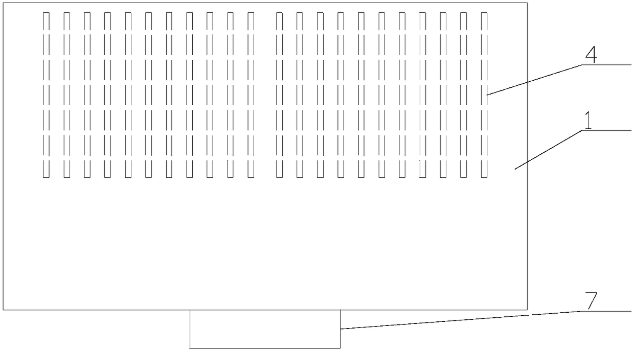
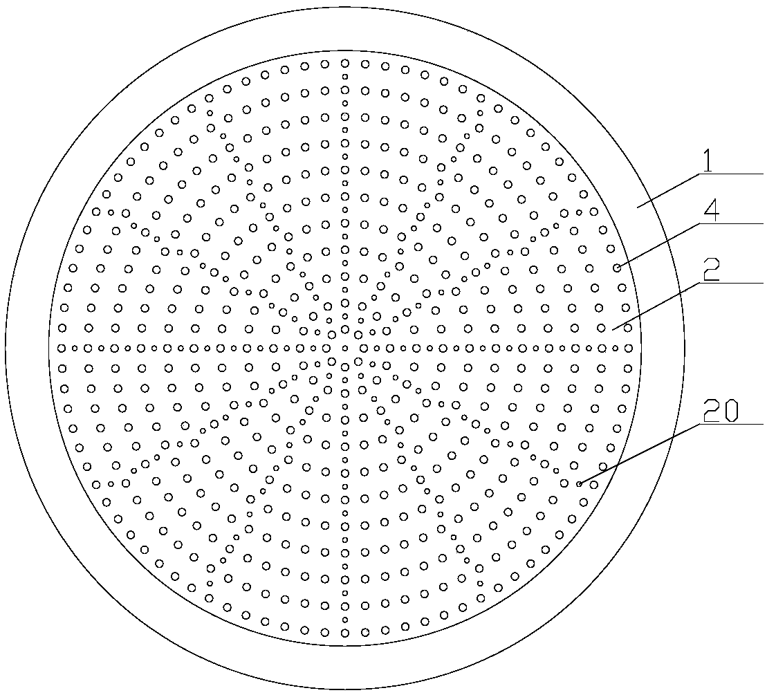
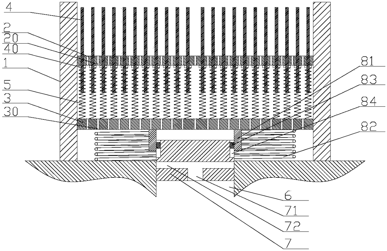
[0028] Embodiment one, such as Figure 3-5 As shown: the linkage assembly includes a sleeve 81 and a compression spring 82, the bottom plate 3 is connected to the inner wall of the base 1 through threads, the air blocking column 7 is connected to the air outlet 6 of the air conditioner through threads, and the blocking The screw thread on the wind post and the screw thread on the bottom plate have the opposite direction of rotation. The sleeve 81 is fixedly connected to the bottom surface of the bottom plate 3 and socketed on the wind blocking post 7. The sleeve 81 and the air blocking post 7 are connected by a synchronous rotation mechanism, and the compression spring 82 is vacantly sleeved outside the sleeve 81 and is pressed between the outer side of the top edge of the air outlet of the air conditioner and the bottom surface of the bottom plate. In this way, when the user further presses down on the cup body, the bottom plate will overcome the force of the compression spri...

Embodiment 2

[0031] Embodiment two, such as Figure 6-8 As shown: the linkage assembly includes an active lever 85, a linkage disk 86, a torsion spring and a driven lever 87. The linkage disk 86 is vertically arranged below the bottom plate 3 and is hinged in the base 1 through a rotating shaft. The two ends of the torsion spring are respectively fixedly connected to the linkage disc 86 and the rotating shaft, the top of the active rod 85 is slidably connected to the bottom surface of the base plate 3, and the bottom end is hinged on the surface of the linkage disc 86, and the driven rod 87 can be A telescopic rod, one end of the driven rod 87 is fixedly connected to the side wall of the wind blocking column 7, and the other end is hinged on the surface of the linkage plate 86, and the active rod 85 and the driven rod 87 are located on the linkage plate 86 respectively. sides of the center. In this way, when the user further presses down on the cup body, the active lever will go down toge...


PUM


Abstract

The invention discloses a built-in cup bracket for a car, and relates to the technical field of car accessories, in particular to a car cup bracket. The built-in cup bracket is ingenious in structure,high in adaptive degree and convenient to use. The built-in cup bracket comprises a cylindrical base, a partition plate, a bottom plate and a plurality of sliding columns. The partition plate is fixedly connected within the base, and located in the middle of the base. The partition plate is connected within the base and located at the lower part of the base. The multiple sliding columns penetratethrough the partition plate. The middles of the sliding columns are provided with limiting rings located below the partition plate. The lower portions of the sliding columns are provided with springsin a sleeved mode. The springs abut against the positions between the limiting rings and the bottom plate. The built-in cup bracket has the characteristics of being ingenious in structure, high in adaptability and convenient to use.

Description

technical field [0001] The invention relates to the technical field of auto parts, in particular to an auto cup holder. Background technique [0002] The cup holder is a commonly used automotive interior part, and its function is to place items such as water cups and mineral water bottles. The existing cup holder and the central control box are integrally injection-molded, and its structure is simple, but the storage space is fixed; in addition, in order to better fix cylindrical objects such as water cups, some cup holders are placed in the storage There are inward protrusions on both sides of the space, but the protrusion structure occupies the storage space and reduces the storage space of the cup holder, which is not suitable for placing some large items. [0003] For this reason, someone has proposed a kind of car cup holder that can deform and be used to support water cup and also can deform and expand space, as the State Intellectual Property Office announced on Sept...

Claims


Application Information

Patent Timeline
IPC IPC(8): B60N3/10
CPCB60N3/104B60N3/105
Inventor 葛健
Owner 葛健
Learn More