Pavement deceleration strip and construction method thereof

A construction method and technology of speed bumps, applied in the directions of roads, roads, road signs, etc., can solve the problems of slow installation efficiency and achieve the effect of speeding up installation efficiency

Inactive Publication Date: 2018-05-29
温州伟国建设有限公司
View PDF5 Cites 4 Cited by
  • Summary
  • Abstract
  • Description
  • Claims
  • Application Information

AI Technical Summary

Problems solved by technology

[0004] However, when aligning the splicing blocks, the alignment is performed pur

Method used


Image

  • Pavement deceleration strip and construction method thereof
  • Pavement deceleration strip and construction method thereof
  • Pavement deceleration strip and construction method thereof

Examples


Embodiment 1

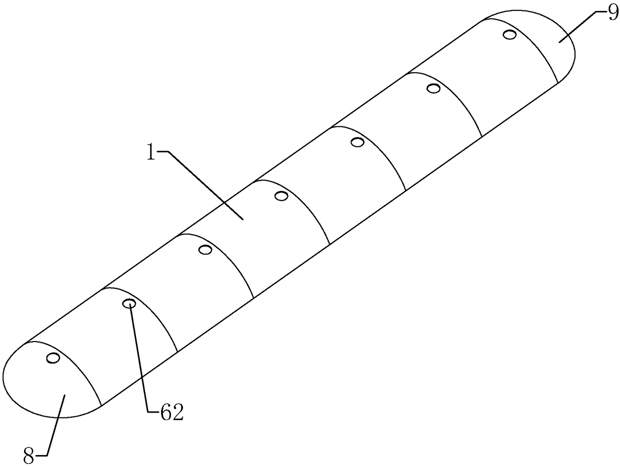
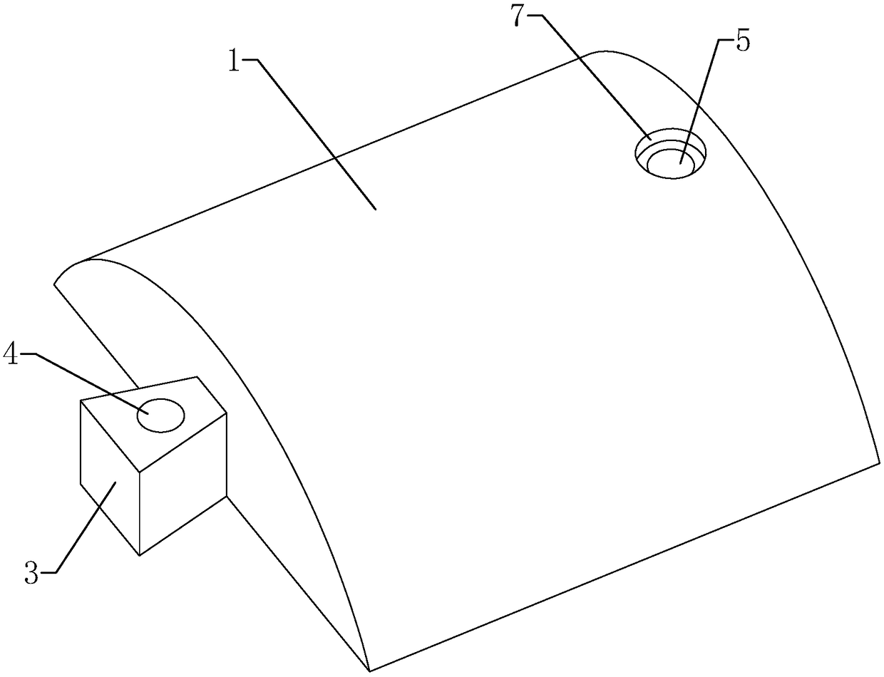
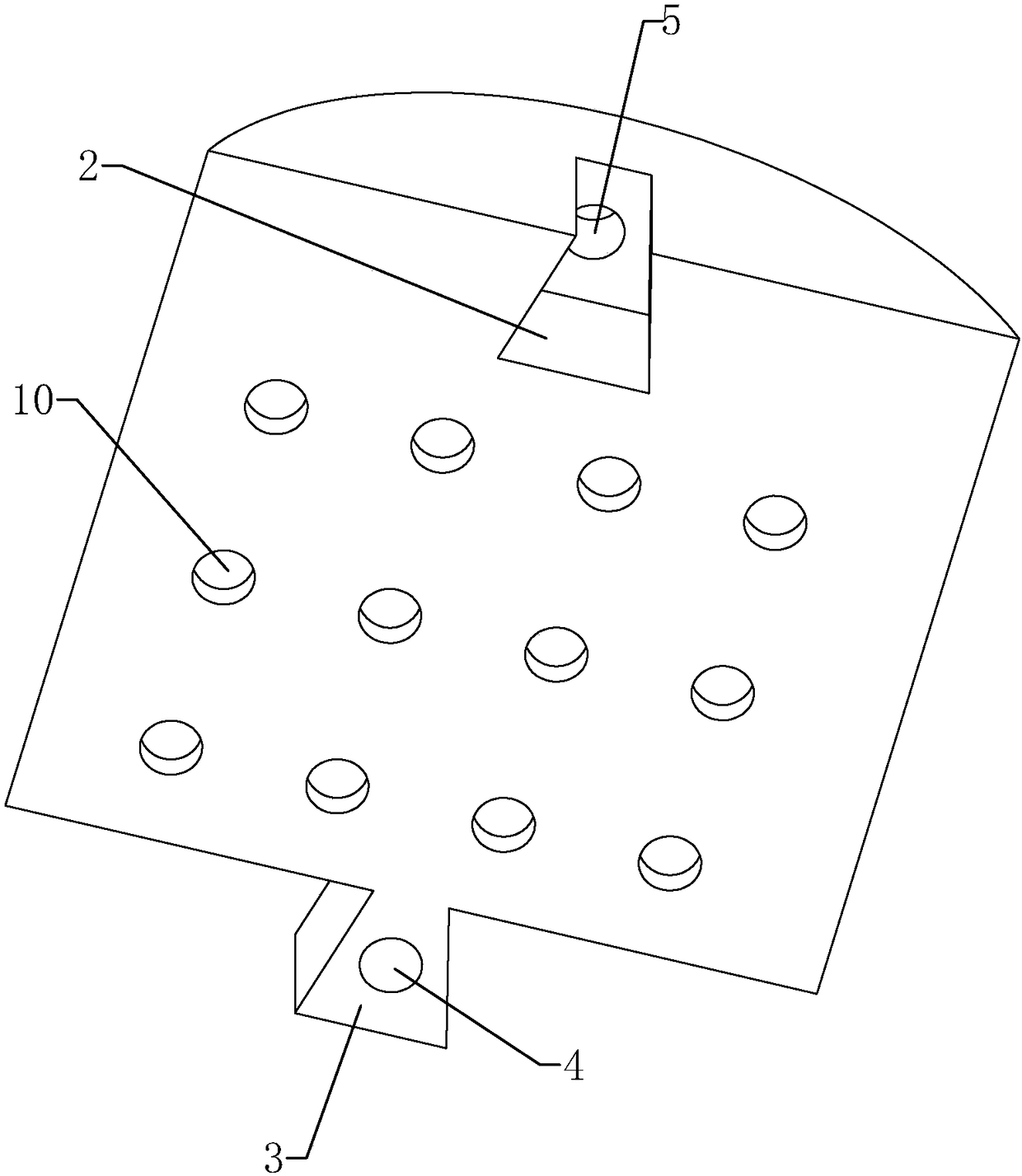
[0035] refer to figure 1 , a road speed bump, comprising a plurality of splicing blocks 1 spliced ​​with each other. refer to figure 2 with 3 One end of each splicing block 1 is provided with a groove 2, and the other end is provided with a protrusion 3. The production of speed bumps can be realized only by making a production mold for splicing block 1 . If both ends of one of the splicing blocks 1 are provided with grooves 2, and both ends of the other splicing block 1 are provided with bumps 3, then two kinds of splicing block 1 production molds need to be made to realize the production of speed bumps. Therefore, the groove 2 and the protruding block 3 are respectively arranged at both ends of each splicing block 1, which can reduce the production cost. One side of the groove 2 runs through the bottom surface of the splicing block 1 and the width of the groove 2 gradually decreases from the bottom of the groove to the notch, so sand and gravel will fall to the ground un...

Embodiment 2

[0040] A construction method of a road speed bump, comprising the following steps:

[0041] Step1: Align the bump 3 of one splicing block 1 with the groove 2 of the other splicing block 1, and drive the two splicing blocks 1 close to each other until the bump 3 snaps into the groove 2 to complete the splicing of the two splicing blocks 1;

[0042] Step2: Repeat Step1 to complete the splicing of all the splicing block 1 and the splicing with the left end block 8 and the right end block 9 to form a complete road speed bump;

[0043] Step3: Clean up the road debris at the location to be installed, place the road speed bump on the road at the location to be installed, use an electric drill to align the concave connection hole 5 and the convex connection hole 4 to drill holes, and form an installation with a depth of 150mm on the road surface hole, put the long nail 6 into the concave connection hole 5 and the convex connection hole 4, and knock the long nail 6 with a hammer to dri...


PUM


Abstract

The invention discloses a pavement deceleration strip and a construction method thereof. The pavement deceleration strip comprises a plurality of splicing blocks spliced mutually and left end-sealingblocks and right end-sealing blocks, wherein the left end-sealing blocks and the right end-sealing blocks are spliced to the two ends of the multiple splicing blocks; in every two adjacent splicing blocks, one of the splicing blocks is provided with a groove, and the other splicing block is provided with a convex block clamped into the groove; and concave connection holes used for penetrating through the splicing blocks are formed in the positions, at the grooves, of the splicing blocks, convex connection holes penetrating through the convex blocks are formed in the positions, at the convex blocks, of the splicing blocks, the concave connection holes and the convex connection holes are coaxial and equal in diameter, and a long nail penetrating into a pavement penetrates into each concave connection hole and the corresponding convex connection hole. The pavement deceleration strip has the beneficial effect that the pavement deceleration strip is convenient to mount, and therefore the mounting efficiency is improved.

Description

technical field [0001] The invention relates to road facilities, in particular to a road speed bump and a construction method thereof. Background technique [0002] At highway crossings, industrial and mining enterprises, schools, residential complex entrances and other road sections that require vehicles to slow down and road sections that are prone to traffic accidents, people often see road speed bumps on the road. The speed bump on the road surface slightly arches the road surface, thereby affecting the driver's driving psychology to achieve the purpose of slowing down the vehicle. [0003] The existing road deceleration belt comprises a plurality of splicing blocks and a left end block and a right end block spliced ​​at both ends of the plurality of splicing blocks. Mounting holes are arranged on the splicing block, the left end block and the right end block. When installing, first arrange multiple splicing blocks in order to form a straight line, and then place the l...

Claims


Application Information

Patent Timeline
IPC IPC(8): E01F9/529
CPCE01F9/529
Inventor 李国贤
Owner 温州伟国建设有限公司
Why Eureka
Try Eureka