Electromagnetic shielding telescopic structure and installation method thereof

A technology of electromagnetic shielding and telescopic structure, applied in the fields of magnetic field/electric field shielding, electrical components, screening cabinets, etc., can solve the problems of large difference in the width of expansion joints, difficult to achieve electromagnetic shielding, front and rear position errors, etc., and achieve fast installation speed. , Not easy to loosen, reduce the weight of the structure and the effect of wind resistance

Active Publication Date: 2018-05-29
中国电波传播研究所 +1
View PDF6 Cites 4 Cited by
  • Summary
  • Abstract
  • Description
  • Claims
  • Application Information

AI Technical Summary

Problems solved by technology

[0002] In modern society, with the development and popularization of electronic technology, the electromagnetic signals generated by electronic equipment are becoming more and more complex and diverse. For occasions with certain requirements on the electromagnetic environment such as bridges, it is necessary to carry out electromagnetic shielding. Due to the expansion joint The common structural forms are mostly metal and rubber composite structures, and the electromagnetic shielding here is difficult to achieve
Due to the unavoidable error of expansion joints caused by construction, there are large errors in the height of adjacent sides of the expansion joints and the front and rear positions, and the width of each expansion joint is quite different. Therefore, the metal structure that can be adjusted in one direction can theoretically meet the shielding requirements , but for expansion joints with large errors, it is difficult to install

Method used


Image

  • Electromagnetic shielding telescopic structure and installation method thereof
  • Electromagnetic shielding telescopic structure and installation method thereof

Examples


Embodiment 1

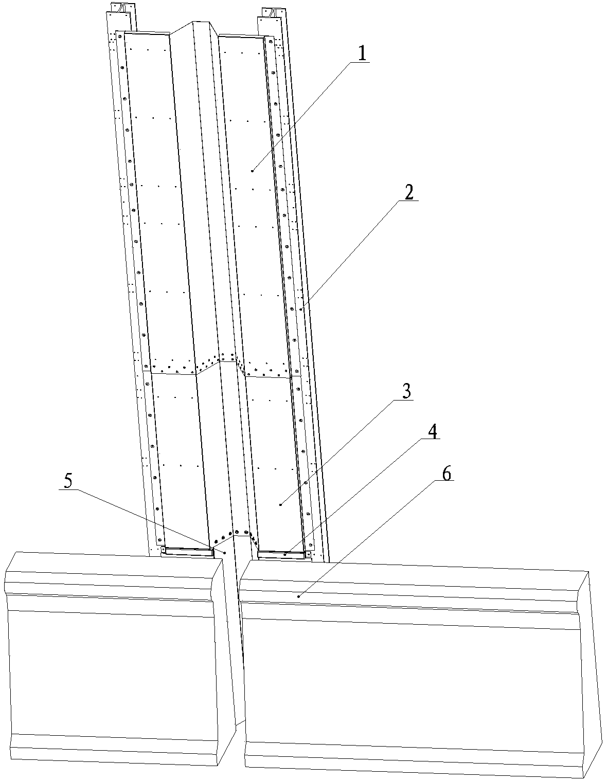
[0021] Example 1, such as Figure 1-2 As shown, this embodiment discloses a telescopic structure for electromagnetic shielding. The structure includes two columns 2 installed vertically on both sides of the expansion joint on the fixed foundation 6, and between the two columns 2 from bottom to top The lower shielding plate 5, the middle shielding plate 3 and the upper shielding plate 1, which are made of elastic materials and have electromagnetic shielding effects, are installed in sequence. The shielding plate 3 is fixedly connected, and is fixedly connected to the fixed base 6 through the rear shielding bead 8, and the middle shielding plate 3 and the upper shielding plate 1 are connected by rivets to form a telescopic shielding unit.

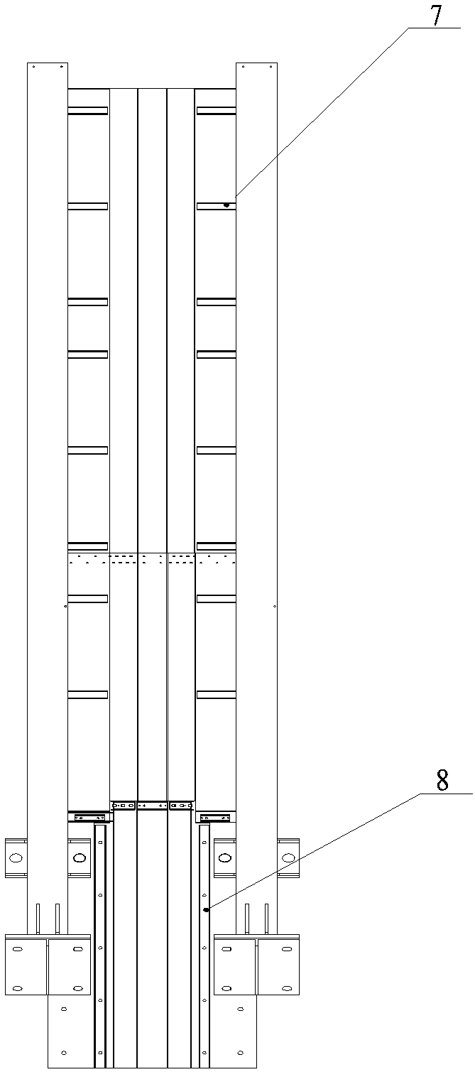
[0022] In this embodiment, the horizontal cross-sectional shape of the lower shielding plate, the middle shielding plate and the upper shielding plate is a stretched shape. Between the two columns 2, more than three support plates 7 arranged...


PUM


Abstract

The invention discloses an electromagnetic shielding telescopic structure and an installation method thereof. The structure includes two vertical columns installed on two sides of an expansion joint on a fixed base. A lower shielding plate, a middle shielding plate and an upper shielding plate which are made of elastic materials and have the function of electromagnetic shielding are orderly installed between the two vertical columns, the lower shielding plate is installed on the expansion joint of the fixed base and is fixedly connected to the middle shielding plate through a front shielding pressing strip and is fixedly connected to the solid base through a back shielding pressing strip, and the middle shielding plate and the upper shielding plate are connected by rivets to form a telescopic shielding unit. According to the electromagnetic shielding telescopic structure, the horizontal cross-section shapes of the lower shielding plate, the middle shielding plate and the upper shielding plate are stretched Pi shapes, the shielding plates can be installed adaptively according to the sizes of different expansion joints during installation, and the versatility is high. According to different requirements, holes can be made in the middle shielding plate and the upper shielding plate to reduce a structural weight and air resistance.

Description

technical field [0001] The invention belongs to the field of electromagnetic shielding, in particular to an electromagnetic shielding telescopic structure and an installation method thereof in the field. Background technique [0002] In modern society, with the development and popularization of electronic technology, the electromagnetic signals generated by electronic equipment are becoming more and more complex and diverse. For occasions with certain requirements on the electromagnetic environment such as bridges, it is necessary to carry out electromagnetic shielding. Due to the expansion joint The common structural forms are mostly metal and rubber composite structures, and the electromagnetic shielding here is difficult to achieve. Due to the unavoidable error of expansion joints caused by construction, there are large errors in the height of adjacent sides of the expansion joints and the front and rear positions, and the width of each expansion joint is quite different....

Claims


Application Information

Patent Timeline
Patent Type & Authority Applications(China)
IPC IPC(8): H05K9/00
CPCH05K9/0007
Inventor 丁振婷
Owner 中国电波传播研究所
Why Eureka
Try Eureka