Terminal block for wire fixing

A terminal and wire fixing technology, which is applied in the direction of conductive connection, connection, and electrical component connection, can solve the problems of waste of resources in the slot of the conductive seat, troublesome cascading of the conductive seat, etc., and achieve the goal of improving reliability and increasing anti-skid performance Effect

Active Publication Date: 2019-12-10
东莞市轩业电子科技有限公司
View PDF6 Cites 0 Cited by
  • Summary
  • Abstract
  • Description
  • Claims
  • Application Information

AI Technical Summary

Problems solved by technology

Due to the limited number of slots on a single conductive seat, when the number of slots on a single conductive seat is not enough, it is necessary to electrically connect two or more conductive seats. The cascading of adjacent conductive seats, that is, the two ends of the cascading line are respectively inserted into one of the sockets of two adjacent conductive seats and fixed, so that the cascading of two or more conductive seats is realized ; However, in the above implementation process, due to the need to use cascading lines to realize the electrical connection between two adjacent conductive seats, there is a shortcoming that the cascading of conductive seats is troublesome, and through the use of cascading lines, the conductive seats need to be reserved One slot is used for the cascading line, which will cause a waste of slot resources on the conductive seat

Method used


Image

  • Terminal block for wire fixing
  • Terminal block for wire fixing
  • Terminal block for wire fixing

Examples


Embodiment Construction

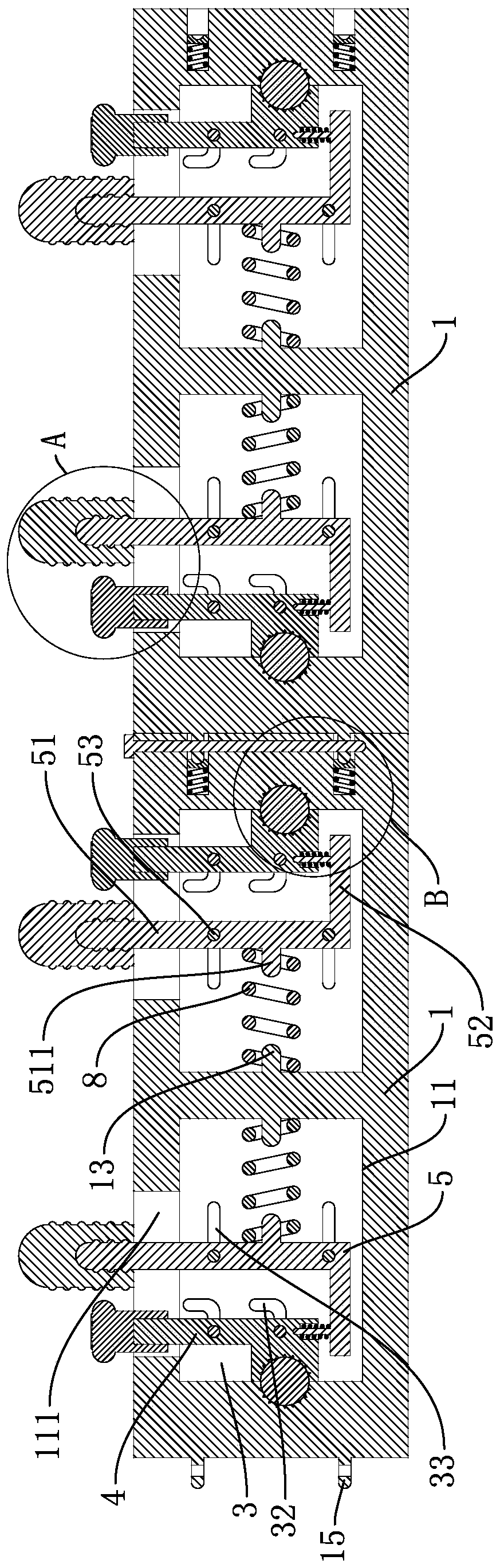
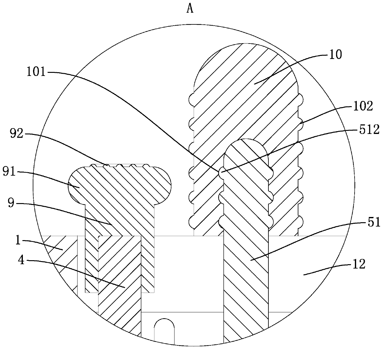
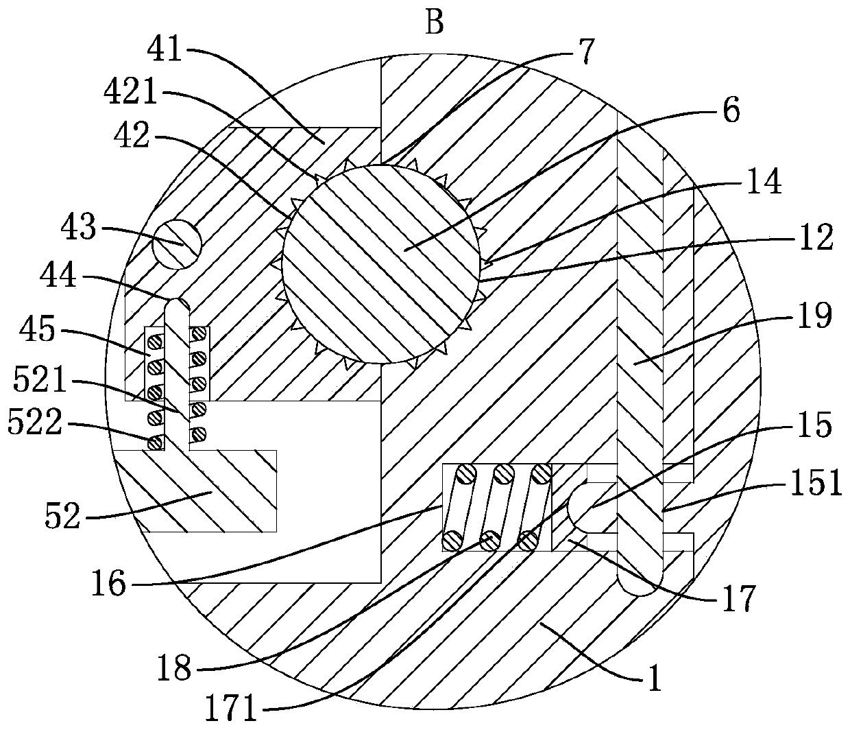
[0019] The specific embodiments of the present invention will be further described in detail below in conjunction with the accompanying drawings.

[0020] In describing the present invention, the terms "up", "down", "left", "right", "front", "rear", "top", "bottom" and the like indicate an orientation or state unless otherwise specified The relationship is based on the orientation or state relationship shown in the drawings, and it is only for the convenience of describing the present invention and simplifying the description, rather than indicating or implying that the mechanism or component referred to must have a specific orientation, be constructed and operated in a specific orientation, therefore It should not be construed as a limitation of the present invention.

[0021] In the description of the present invention, it should be noted that unless otherwise specified and limited, the term "connection" should be understood in a broad sense, for example, it can be a fixed c...


PUM


Abstract

The invention discloses a terminal for fixing a lead. The terminal comprises a conductive seat. The outside wall at one end of the conductive seat is provided with a pair of conductive rods. The outside wall at the other end of the conductive seat is provided with a blind hole for insertion of the conductive rods on the adjacent terminals for fixing the lead. A conductive block is slidably connected in the blind hole. A third spring which is used for pushing the conductive block so that the conductive block abuts against the conductive rods on the adjacent terminals for fixing the lead. An anchor pole for locking the conductive seat and the conductive rods on the adjacent terminals for fixing the lead after the conductive rods on the adjacent terminals for fixing the lead is inserted intothe conductive seat. The conductive rod is provided with a through hole which can be penetrated by the anchor rod. The terminal for fixing the lead can conveniently realize cascading of two or more conductive seats without a cascading wire, thereby facilitating cascading of the conductive seat and preventing waste of wire duct resource on the conductive seat.

Description

technical field [0001] The invention belongs to the technical field of wire connection devices, and relates to a wire fixing terminal. Background technique [0002] In the process of electrical connection of wires, it is often necessary to use terminal blocks to realize the electrical connection of two or more wires. The current terminal blocks generally include a conductive seat, and there are several slots for the insertion of wires in the conductive seat. Each slot is threaded with bolts for pressing the wires inserted into the slots. After the wires are inserted into the slots, the wires are fixed by tightening the bolts. After the wires are fixed, the The electrical connection of two or more wires. Due to the limited number of slots on a single conductive seat, when the number of slots on a single conductive seat is not enough, it is necessary to electrically connect two or more conductive seats. The cascading of adjacent conductive seats, that is, the two ends of the...

Claims


Application Information

Patent Timeline
Patent Type & Authority Patents(China)
IPC IPC(8): H01R11/01H01R11/09H01R4/48H01R4/00
CPCH01R4/4863H01R4/4872H01R4/54H01R11/01H01R11/09
Inventor 沈惠萍
Owner 东莞市轩业电子科技有限公司
Why Eureka
Try Eureka