Manipulator device for automatic supply

An automatic feeding and manipulator technology, applied in the field of manipulators, can solve the problems of high cost, low precision, complex manipulator design, etc., and achieves the effect of simple structure, avoiding excessive force and saving labor in clamping.

Inactive Publication Date: 2017-02-15
ANHUI ZHILIANG INVESTMENT GRP
View PDF0 Cites 5 Cited by
  • Summary
  • Abstract
  • Description
  • Claims
  • Application Information

AI Technical Summary

Problems solved by technology

[0003] At present, most of the loading and unloading devices are operated by manipulators instead of manual operations, but in the actual use process, the structural design of manipulators is relatively complicated, and generally has the disadvantages of high cost and low precision.

Method used


Image

  • Manipulator device for automatic supply
  • Manipulator device for automatic supply
  • Manipulator device for automatic supply

Examples


Embodiment Construction

[0022] The following will clearly and completely describe the technical solutions in the embodiments of the present invention with reference to the accompanying drawings in the embodiments of the present invention. Obviously, the described embodiments are only some, not all, embodiments of the present invention.

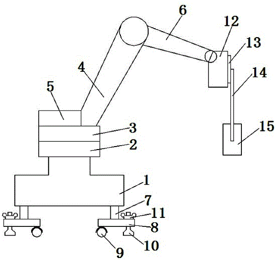
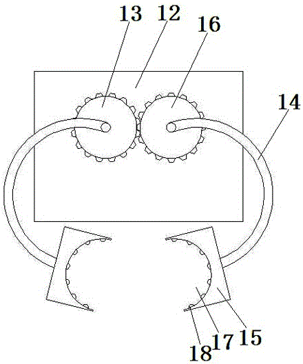
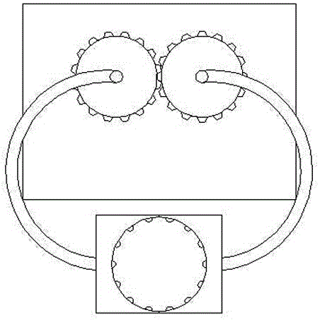
[0023] refer to Figure 1-3 , a manipulator device for automatic feeding, comprising a base 1, the upper end of the base 1 is provided with a rotating base 2, the upper end of the rotating base 2 is provided with an arm mounting base 3, and the arm mounting base 3 is connected to the main One end of the arm 4 is connected, and the arm mount 3 is provided with a counterweight 5 to keep the overall stability of the device. The other end of the main arm 4 is connected to one end of the auxiliary arm 6, wherein the connection between the arm mount 3 and the main arm 4, and the connection between the main arm 4 and the auxiliary arm 6 are internally provided with an air m...


PUM


Abstract

The invention discloses a manipulator device for automatic supply. The manipulator device comprises a stand; a rotating base is arranged at the upper end of the stand; an arm mounting base is arranged at the upper end of the rotating base, and is connected with one end of a main arm; the other end of the main arm is connected with one end of a secondary arm; the other end of the secondary arm is hinged with a grabbing device; the grabbing device includes a grabbing base, a driving gear, a driven gear, a mechanical arm and a clamping jaw; a driving gear and a driven gear, mutually engaged, are movably mounted on the frontal surface of the grabbing base; mechanical arms are respectively fixed in the center positions of the driving gear and the driven gear; the mechanical arms are arched; clamping jaws are respectively arranged at the end parts of the two mechanical arms; semicircular clamping grooves are respectively formed in the inner sides of the two clamping jaws; and the driving gear is in transmission connection with a driving device.

Description

technical field [0001] The invention relates to a manipulator, in particular to a manipulator device for automatic feeding. Background technique [0002] As the earliest industrial robot, the manipulator is widely used in machinery manufacturing, metallurgy, electronics, light industry and other industries because it can replace human heavy labor, realize mechanization and automation of production, and can operate in dangerous situations to protect personal safety. . [0003] At present, most of the loading and unloading devices are operated by manipulators instead of manual operations, but in the actual use process, the structural design of manipulators is relatively complicated, and generally has the disadvantages of high cost and low precision. Contents of the invention [0004] The purpose of the present invention is to solve the shortcoming existing in the prior art, and propose a kind of manipulator device of automatic feeding. [0005] In order to achieve the abov...

Claims


Application Information

Patent Timeline
IPC IPC(8): B25J9/00B25J15/08
CPCB25J9/00B25J9/0009B25J15/08
Inventor 王卫华
Owner ANHUI ZHILIANG INVESTMENT GRP
Why Eureka
Try Eureka