Cutting chip breaking device with active power

A power and chip breaking technology, applied in auxiliary devices, turning equipment, manufacturing tools, etc., can solve the problems of tool damage, low chip breaking efficiency, and easy damage to machine tools, so as to improve efficiency and reliability, and achieve good chip breaking effect of effect

Inactive Publication Date: 2018-06-05
TAIYUAN UNIV OF TECH
View PDF7 Cites 3 Cited by
  • Summary
  • Abstract
  • Description
  • Claims
  • Application Information

AI Technical Summary

Problems solved by technology

[0002] Turning is the most popular and basic processing method in the world of mechanical processing. In the cutting process, the broken chips will splash and hurt people, and it is easy to damage the machine tool; while the long strip-shaped chips will be wrapped around the workpiece or the tool. It is easy to scratch the workpiece, cause tool damage, and even affect the safety of workers. Chips are difficult to clean and transport due to curling, which greatly increases the difficulty and cost of post-processing
At the same time, the traditional chip breaking methods such as the chip breaker are passive chip breaking, the effect is often not obvious, the reliability of chip breaking is unstable, the efficiency of chip breaking is not high, and it is difficult to adapt to the occasions where the tool angle and cutting amount change

Method used


Image

  • Cutting chip breaking device with active power
  • Cutting chip breaking device with active power
  • Cutting chip breaking device with active power

Examples


Embodiment 1

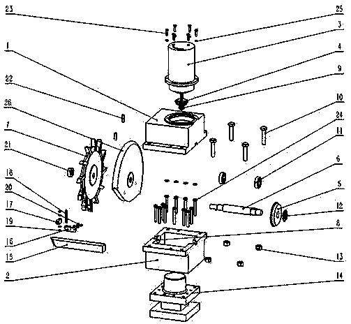
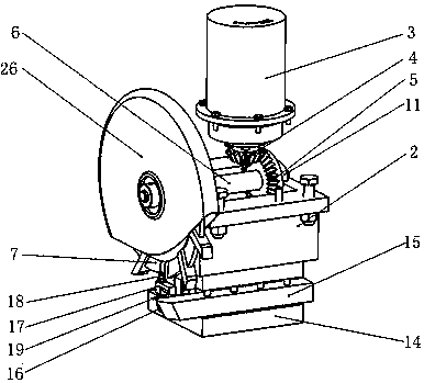
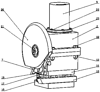
[0029] like Figure 1-7 As shown, a cutting chip breaking device with active power includes an upper casing 1, a lower casing 2, a DC speed regulating motor 3, a small bevel gear 4, a large bevel gear 5, an output shaft 6, and a three-sided edge milling cutter 7. Bearing 11, protective cover 26, base 16, "L" type block 17, guide stud 18; wherein DC speed regulating motor 3 is the power source of the whole chip breaking device with active power; output shaft 6 is The power is provided by the rotation of the side and side milling cutter.

[0030] A bearing seat hole 8 is processed on both sides of the upper and lower shells, and two bearings 11 are respectively installed in the two bearing seat holes 8; the output shaft 8 is supported by two bearings 11, and a three-side milling cutter 7 is installed on one end, and the middle part The large bevel gear 5 is installed; the small bevel gear 4 is installed at the output end of the DC speed regulating motor;

[0031] There are 8 e...


PUM


Abstract

The invention belongs to the field of machining, and particularly relates to a cutting chip breaking device with active power. The cutting chip breaking device comprises an upper casing, a lower casing, a DC speed regulating motor, a three-edge milling cutter, a knife rest, a turning tool, a protective cover, a base, an L-shaped check block and a guide stud. The DC speed regulating motor is mounted on the upper casing and is connected with the three-edge milling cutter through a transmission structure, the outer side of the three-edge milling cutter is provided with the protective cover, the lower casing is mounted on the lower side of the upper casing and installed on the knife rest, the knife rest is also provided with the turning tool, the base is fixed on the side of the turning tool through a base bolt, the upper surface of the base is provided with a threaded hole, one end of the guide stud is screwed into the threaded hole, the L-shaped check block is mounted on the guide stud,the L-shaped check block can move up and down and rotate along the guide stud, and the L-shaped check block is disposed below the three-edge milling cutter. According to the cutting chip breaking device, an adjustment can be made according to different cutter angles and cutting amounts, which greatly improves the efficiency and reliability of chip breaking.

Description

technical field [0001] The invention belongs to the field of mechanical processing, in particular to a cutting chip breaking device with active power. Background technique [0002] Turning is the most popular and basic processing method in the world of mechanical processing. In the cutting process, the broken chips will splash and hurt people, and it is easy to damage the machine tool; while the long strip-shaped chips will be wrapped around the workpiece or the tool. It is easy to scratch the workpiece, cause tool damage, and even affect the safety of workers. Chips are difficult to clean and transport due to curling, which greatly increases the difficulty and cost of post-processing. At the same time, traditional chip breaking methods such as chip breakers are passive chip breaking, the effect is often not obvious, the reliability of chip breaking is unstable, the efficiency of chip breaking is not high, and it is difficult to adapt to the occasions where the tool angle an...

Claims


Application Information

Patent Timeline
Patent Type & Authority Applications(China)
IPC IPC(8): B23B25/02
CPCB23B25/02Y02P70/10
Inventor 郭文亮丁艳红张天翼王晋凤刘润爱宫晓琴郑进花
Owner TAIYUAN UNIV OF TECH
Why Eureka
Try Eureka