Gas burner with multiple flame rings for cooking hobs

A gas burner and burner technology, which is applied in the directions of gas fuel burners, burners, combustion types, etc., can solve problems such as the significant overall size of the burner

Active Publication Date: 2019-09-17
E G O 电动工具有限公司
View PDF6 Cites 0 Cited by
  • Summary
  • Abstract
  • Description
  • Claims
  • Application Information

AI Technical Summary

Problems solved by technology

Moreover, the two venturis extend outwards with respect to the volume defined by said outer annular burner base and this imposes a series of restrictions on the method of mounting the burner on the cooktop and in any case leads to The overall size of the burner is significantly

Method used


Image

  • Gas burner with multiple flame rings for cooking hobs
  • Gas burner with multiple flame rings for cooking hobs
  • Gas burner with multiple flame rings for cooking hobs

Examples


Embodiment Construction

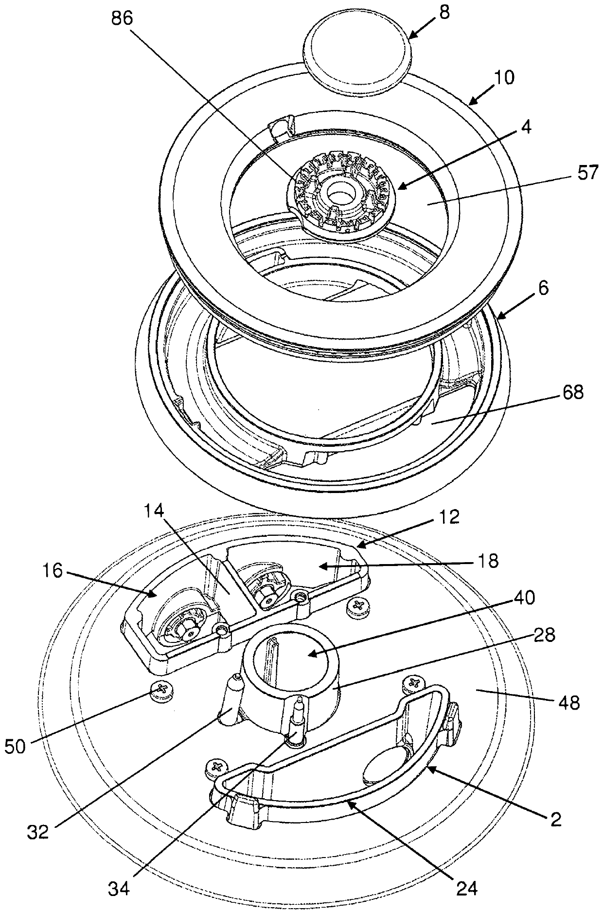
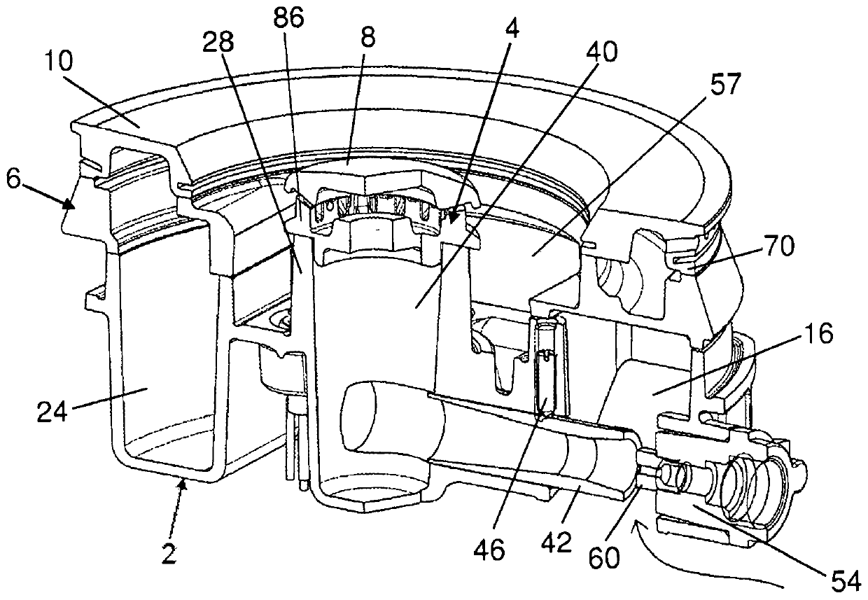
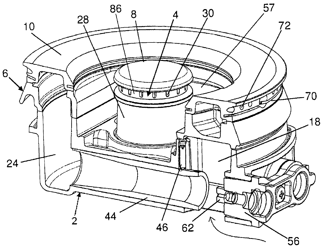
[0044] As shown in the figure, the burner according to the present invention includes:

[0045] - the lower burner body 2 intended to be applied under the metal plate 48 of the cooktop and fixed to said metal plate 48 by eg screws 50,

[0046] - the first burner base 4 for the central flame ring integrated with the lower burner body 2,

[0047] - a second burner base 6 for one or two annular flame rings, conveniently constituted by a separate body from the first burner base 4,

[0048] - round cover 8 for first burner base 4,

[0049] - An annular cover 10 for the second burner base 6 .

[0050] Advantageously, the lower body 2 consists of a single part. Conveniently, it has an irregular shape but preferably has an outer edge inscribed in the circumference. Preferably, the lower body 2 has a shape in plan view that can be conceived to be produced by an almost circular shape but lacks two diametrically opposed circular segments at the edge 7 that reinforces the two opposed ...


PUM


Abstract

A multi-flame ring gas burner for cooktops, wherein the first burner base (4) is integrated with said protruding tubular portion (28) of the lower burner body (2), provided with At least one injector bracket unit (52) can be applied to the lower burner body (2) in two parts (54, 56) which can be removably inserted into corresponding through-holes (20, 22) obtained in said burner body (2) in a position facing a tubular element (42, 44) internally formed as a linear venturi ).

Description

technical field [0001] The present invention relates to a multi-flame ring gas burner for cooktops. Background technique [0002] Gas burners for cooktops with two or more main flame rings are known; these burners have an inner circular portion generating an inner flame ring and one or two flame rings (which are identical to the The flame ring generated by the inner circular portion is concentric) to the outer annular portion. [0003] Typically, burners of this type may have one or more injectors from which a flow of gas is released, the flow of which is controlled by a valve which is actuated by a user via a knob. [0004] In the case of a single injector or multiple injectors connected to a single outlet of a valve through which all flame rings are simultaneously regulated, and the burner is often referred to as a "multi-ring" burner. [0005] On the other hand, in the case of multiple injectors connected to two different outlets of the valve, the burner ring can be adj...

Claims


Application Information

Patent Timeline
Patent Type & Authority Patents(China)
IPC IPC(8): F23D14/04F23D14/06F23D14/58
CPCF23D2900/14062F24C3/085F23D14/065F23D14/64F23D2203/007F24C3/082
Inventor C·比亚吉奥利L·布雷西亚M·斯巴菲W·诺特
Owner E G O 电动工具有限公司
Why Eureka
Try Eureka