
Method, device and program to display 3D representations of an object based on orientation information of the display

An orientation and object technology, applied in the field of 3D representation, equipment and programs based on the orientation information of the display, can solve the problems of difficult low-memory device implementation and large number of images

Active Publication Date: 2018-06-08
APPLE INC
View PDF6 Cites 1 Cited by
  • Summary
  • Abstract
  • Description
  • Claims
  • Application Information

AI Technical Summary

Problems solved by technology

What should be relatively easy to grasp is that the number of images required for either of the first two methods can become very large – making it difficult to implement in low-memory devices

Method used


Image

  • Method, device and program to display 3D representations of an object based on orientation information of the display
  • Method, device and program to display 3D representations of an object based on orientation information of the display
  • Method, device and program to display 3D representations of an object based on orientation information of the display

Examples


Embodiment Construction

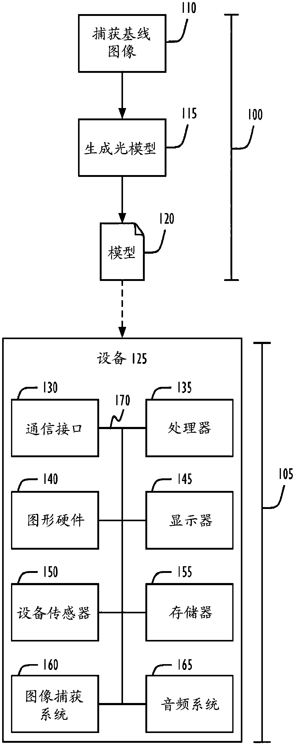
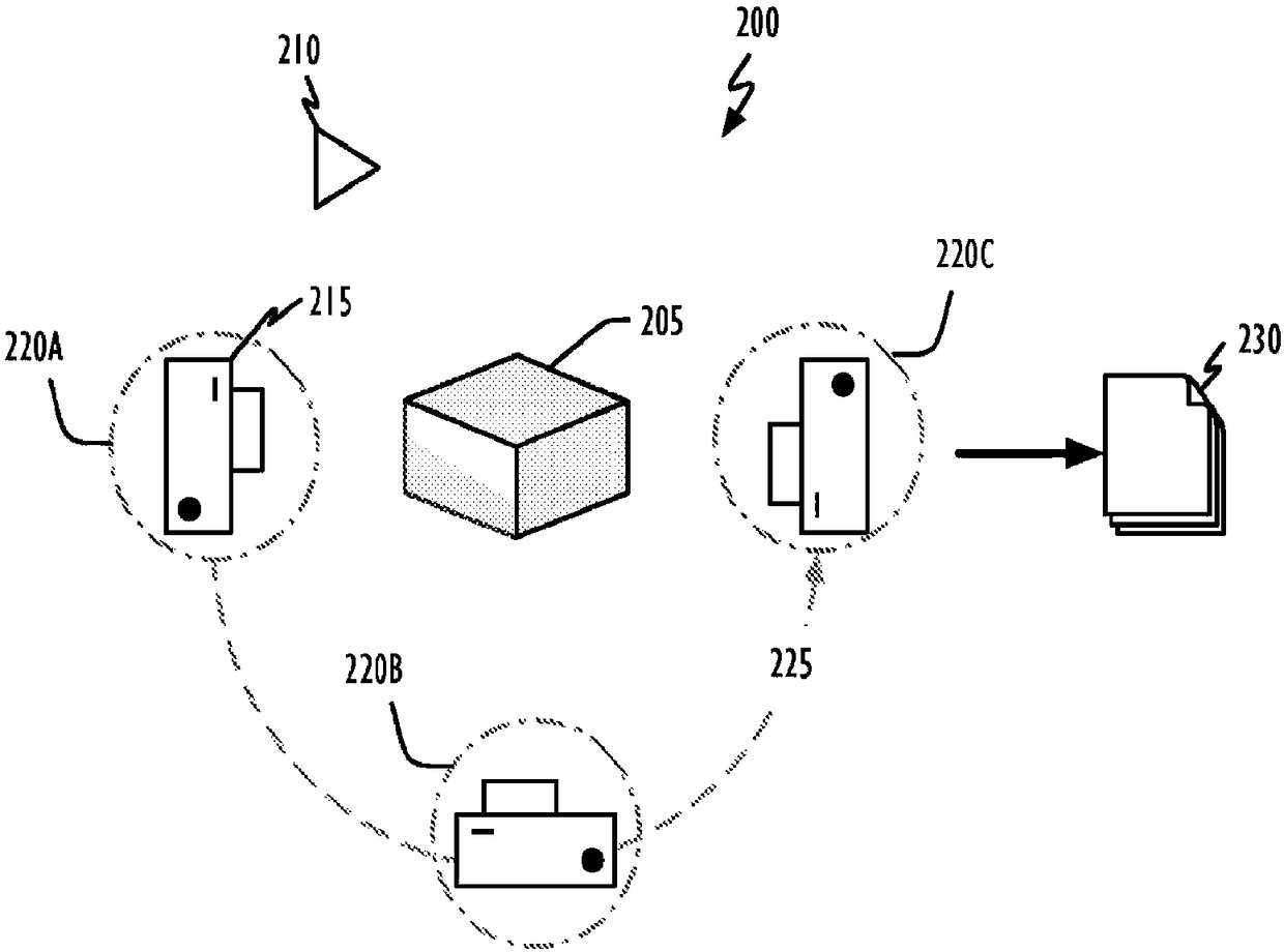
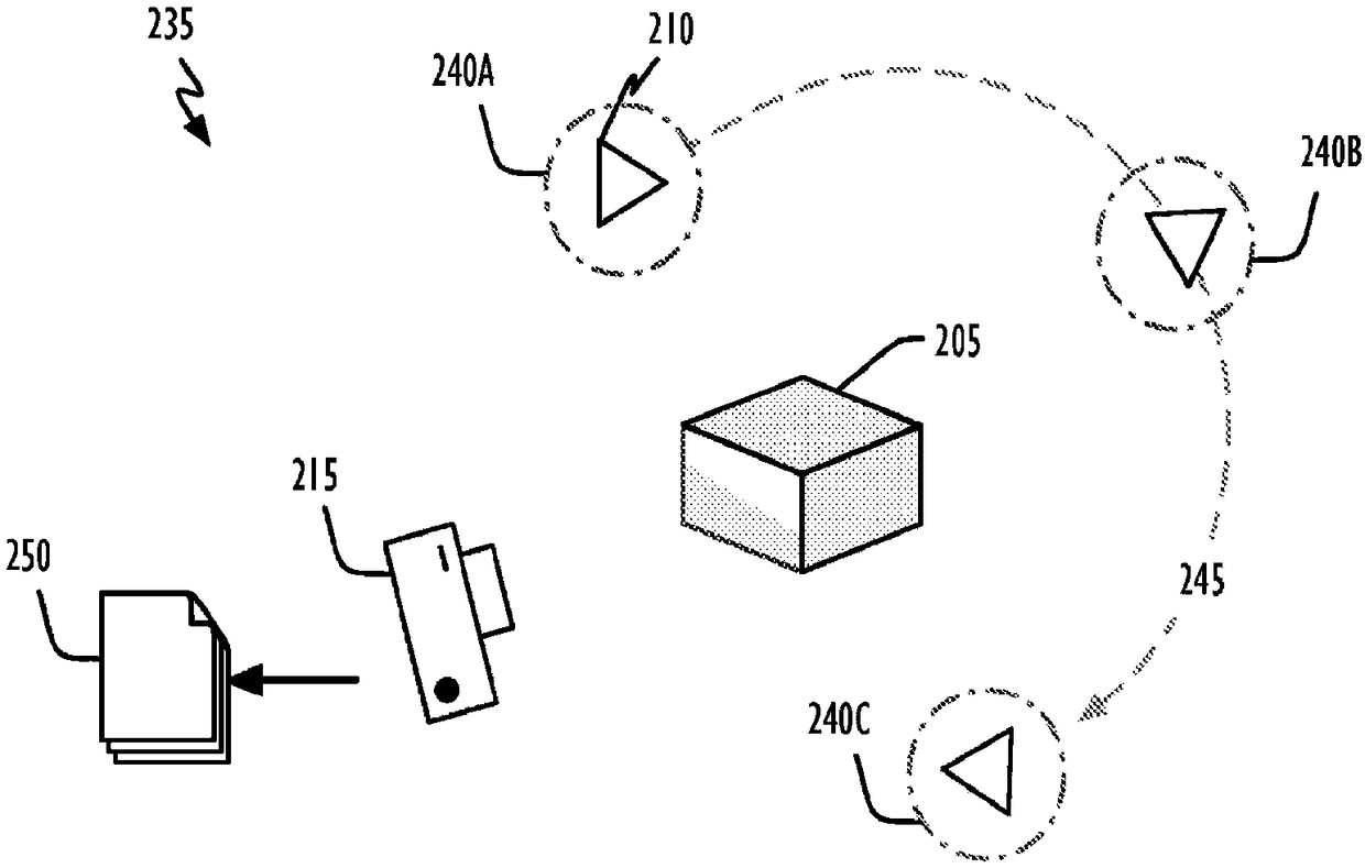
[0010] The present disclosure relates to systems, methods, and computer-readable media for displaying graphical elements that exhibit three-dimensional (3D) behavior. In general, techniques are disclosed for displaying graphical elements in a manner that simulates full 3D visibility, including parallax and shadows. More specifically, a plurality of images captured, each having a known spatial relationship to the target 3D object, may be used to construct a lighting model of the target object. For example, in one embodiment, this can be accomplished using polynomial texture mapping (PTM) using spherical or hemispherical harmonics. Relatively few base images can be identified using PTM technology. When the target object is to be displayed, the orientation information may be used to generate a combination of base images in order to simulate a 3D representation of the target object—in some embodiments, using shadows and parallax distortion. Orientation information may be obtaine...


PUM


Abstract

Techniques are disclosed for displaying a graphical element in a manner that simulates three-dimensional (3D) visibility (including parallax and shadowing). More particularly, a number of images, each captured with a known spatial relationship to a target 3D object, may be used to construct a lighting model of the target object. In one embodiment, for example, polynomial texture maps (PTM) using spherical or hemispherical harmonics may be used to do this. Using PTM techniques a relatively small number of basis images may be identified. When the target object is to be displayed, orientation information may be used to generate a combination of the basis images so as to simulate the 3D presentation of the target object.

Description

Background technique [0001] The practical display of three-dimensional (3D) objects on two-dimensional (2D) surfaces has been a long-standing goal in the field of image processing. One way to simulate a 3D object is to take a large number of images each lit from a different position. A particular image can then be selected and displayed based on the detected position of the light source (eg, via an ambient or colored light sensor). Another approach is to take a large number of images each with a 3D object at different positions relative to a fixed light source. Again, a particular image can be selected and displayed based on the determined orientation of the 3D object (eg, by using an accelerometer). Another method combines the above two methods so that both lighting position and object orientation can be considered. What should be relatively easy to grasp is that the number of images required for either of the first two methods can become very large - making it difficult t...

Claims


Application Information

Patent Timeline
IPC IPC(8): G06T15/20G06T15/50
CPCG06T15/205G06T15/60G06T15/50G06T15/20G06T15/506G06T2215/16G06V40/161G06F3/0346
Inventor R·莫塔L·R·杨格斯M·金
Owner APPLE INC
Features
  • Generate Ideas
  • Intellectual Property
  • Life Sciences
  • Materials
  • Tech Scout
  • Unparalleled Data Quality
  • Higher Quality Content
  • 60% Fewer Hallucinations
Learn More