Switch and its manufacturing method

A switch and opening technology, which is applied in the direction of electrical switches, key modules, contact surface shape/structure, etc., to achieve the effect of suppressing depression

Active Publication Date: 2019-10-18
FUJIKURA LTD
View PDF8 Cites 0 Cited by
  • Summary
  • Abstract
  • Description
  • Claims
  • Application Information

AI Technical Summary

Problems solved by technology

In this case, the upper and lower electrodes are close to each other, and the switch may be accidentally turned on.

Method used


Image

  • Switch and its manufacturing method
  • Switch and its manufacturing method
  • Switch and its manufacturing method

Examples


Embodiment Construction

[0038] Embodiments of the present invention will be described below with reference to the drawings.

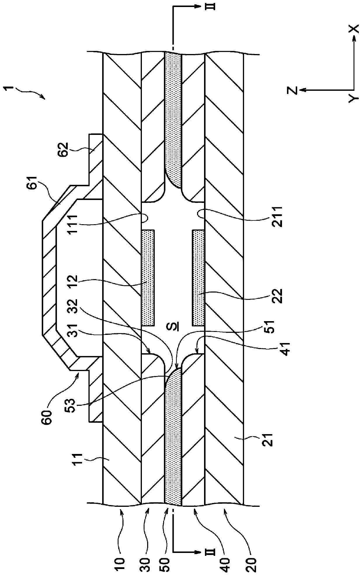
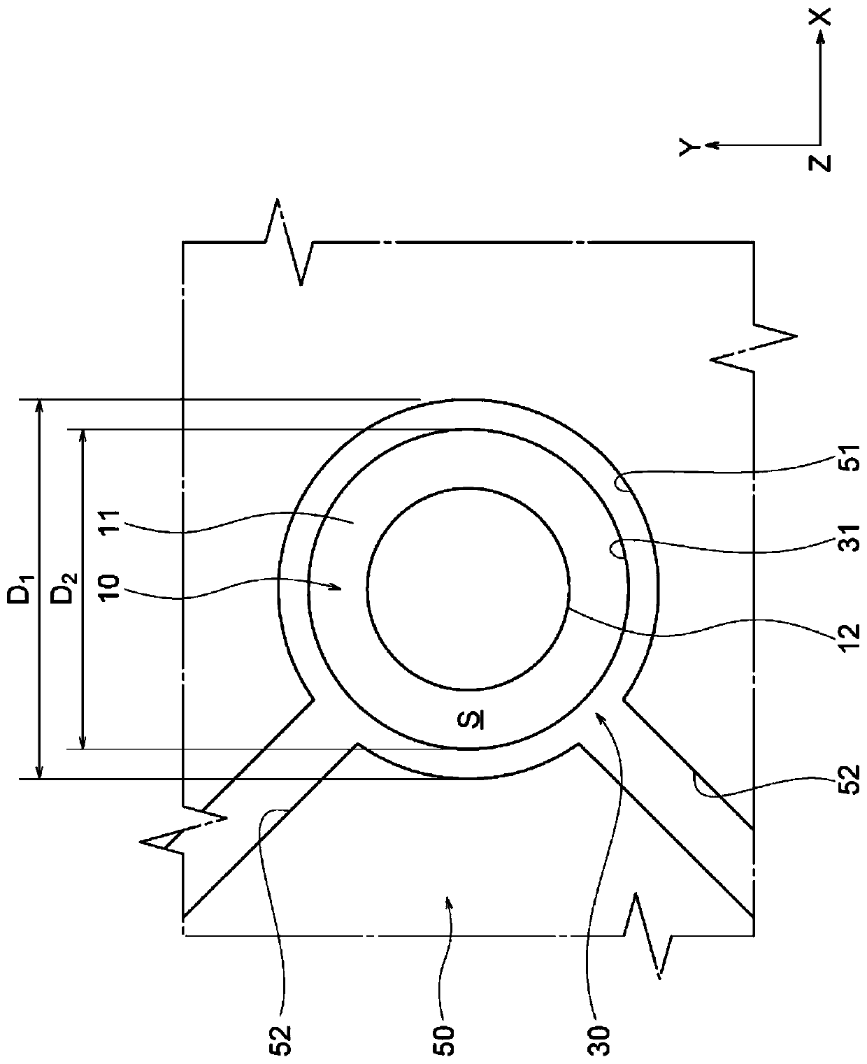
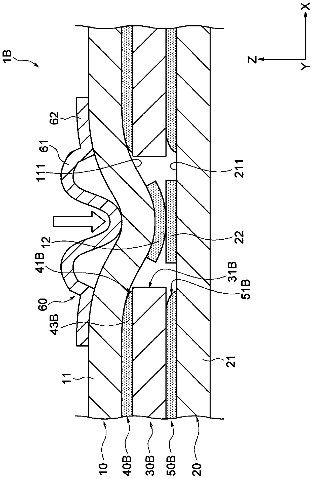
[0039] figure 1 is a cross-sectional view showing the membrane switch 1 according to the first embodiment of the present invention, figure 2 is along figure 1 A top view of the line II-II.

[0040] Such as figure 1 as well as figure 2 As shown, the membrane switch 1 of the present embodiment includes an upper electrode sheet 10 , a lower electrode sheet 20 , an adhesive layer 50 , and a rubber dome 60 as a pressing member. The upper electrode sheet 10 includes an upper substrate 11 , an upper electrode 12 , and an upper insulating layer 30 . In addition, the lower electrode sheet 20 includes a lower base material 21 , a lower electrode 22 , and a lower insulating layer 40 . In this membrane switch 1 , the upper insulating layer 30 is formed on the lower surface 111 of the upper base material 11 of the upper electrode sheet 10 , and the upper insulating layer 30 is form...


PUM


Abstract

A membrane switch includes an upper electrode sheet that includes an upper electrode, a lower electrode sheet that includes a lower electrode facing the upper electrode, and an adhesive layer that joins the upper electrode sheet to the lower electrode sheet; and the upper and lower electrodes come into contact with each other due to a pressing force, which is applied to at least one of the upper electrode sheet and the lower electrode sheet, and conduct electricity. The upper electrode sheet includes: an upper base on which the upper electrode is formed; and an upper insulating layer that is provided between the upper base and the lower electrode sheet, includes a first opening at a position corresponding to the upper electrode, and is joined to the lower electrode sheet by the adhesive layer. The upper insulating layer is formed on the upper base.

Description

technical field [0001] The present invention relates to switches and methods of manufacturing the same. [0002] For the designated countries that approve the introduction by reference of documents, the content described in Japanese Patent Application No. 2015-248390 filed in Japan on December 21, 2015 is incorporated into this specification by reference and forms a part of this specification. Background technique [0003] Known have following switch, this switch is provided with: the electrode sheet of upper and lower sides; Spacer, it is arranged between the electrode sheet of up and down and forms the desired interval between the electrode sheet of up and down, and the electrode sheet of up and down is separated from spacer. objects are bonded via an adhesive (for example, refer to Patent Document 1). In the switch described in Patent Document 1, an opening for allowing upper and lower electrodes to come into contact is formed in the spacer, and an adhesive is provided a...

Claims


Application Information

Patent Timeline
Patent Type & Authority Patents(China)
IPC IPC(8): H01H13/703H01H13/712
CPCH01H13/703H01H2209/046H01H2211/004H01H2211/018H01H2229/002H01H2229/058H01H1/06H01H11/04H01H13/10H01H13/14H01H2233/07
Inventor 松岛康介立川泰之田中涉
Owner FUJIKURA LTD
Why Eureka
Try Eureka