Eureka AIR delivers breakthrough ideas for toughest innovation challenges, trusted by R&D personnel around the world.

Fixing device for iron automobile part block body polishing mechanism

A technology for automobile parts and grinding mechanisms, applied in grinding/polishing safety devices, grinding workpiece supports, grinding/polishing equipment, etc., can solve problems such as poor safety, low efficiency, uneven grinding, etc. Mechanical automatic grinding, reduce environmental pollution, and fix firmly

Inactive Publication Date: 2018-06-12
FOSHAN RUIPUDA OPTOELECTRONICS TECH CO LTD
View PDF0 Cites 5 Cited by
  • Summary
  • Abstract
  • Description
  • Claims
  • Application Information

AI Technical Summary

Problems solved by technology

[0002] Existing iron automobile small parts need to be polished after being grooved in the middle, while the existing grinding is generally manual grinding, which requires manual fixing of the parts by bolts to the compacting block to fix the parts on the The pressing blocks are fixed or people hold it while grinding, the efficiency is low, and the grinding is not uniform, which affects the quality and poor safety;
[0003] Moreover, the waste and dust produced by grinding have no material receiving place. Generally, the tools are on the platen or bottom surface, which affects the environment.

Method used


Image

  • Fixing device for iron automobile part block body polishing mechanism
  • Fixing device for iron automobile part block body polishing mechanism

Examples


Embodiment

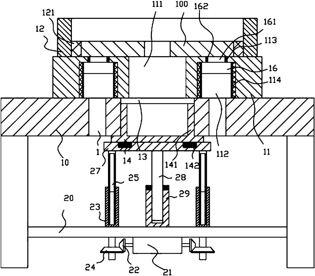
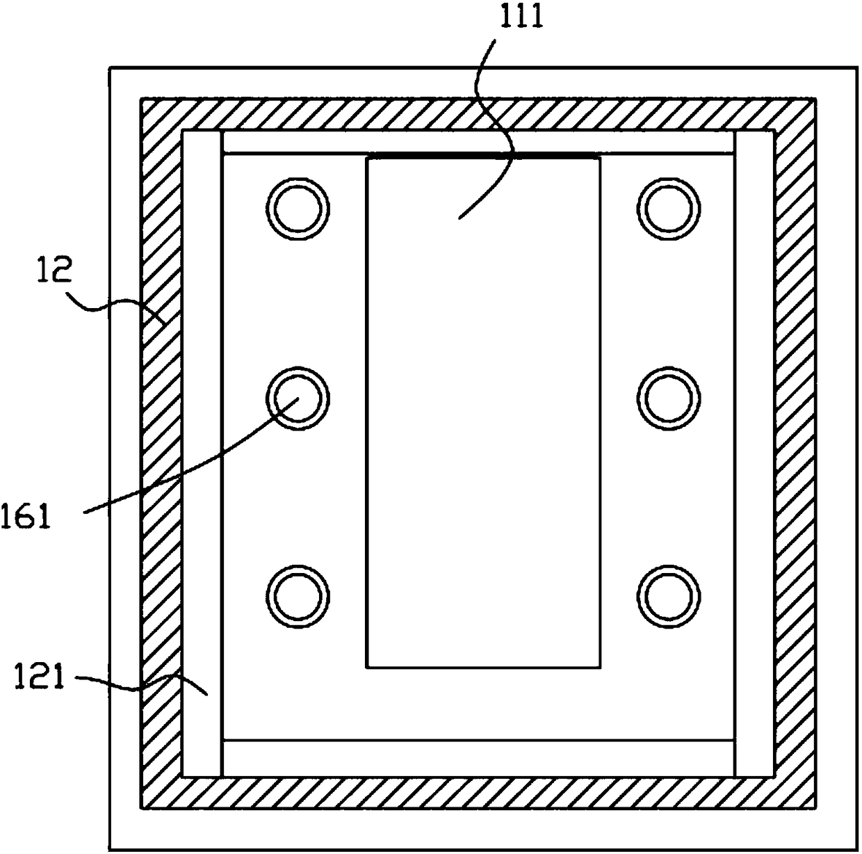
[0019] Example: see Figure 1 to Figure 2 As shown, a fixing device for an iron automobile parts block grinding mechanism includes a frame 10, a main placement block 11 is fixed in the middle of the top surface of the top plate of the frame 10, and a rectangular shape is fixed on the top surface of the main placement block 11. Frame 12, the middle part of the main placement block 11 has an auxiliary telescopic channel 111, and the top plate of the frame 10 directly below the auxiliary telescopic channel 111 is formed with a waste material blanking channel 13, and directly below the top plate of the frame 10 A lower base plate 20 is provided, and the lower base plate 20 is fixed on the inner side wall of the lower leg of the frame 10. The middle bottom surface of the lower base plate 20 is fixed with a double output shaft motor 21, and the left and right output shafts of the double output shaft motor 21 are fixed Drive bevel gear 22 is arranged, and two lifting screw sleeves 23...


PUM


Abstract

The invention discloses a fixing device for an iron automobile part block body polishing mechanism. The fixing device comprises a rack; a main placing block is fixedly arranged at the middle part of the top surface of a top plate of the rack; a rectangular frame is fixedly arranged on the top surface of the main placing block; an auxiliary telescopic through groove is formed in the middle part ofthe main placing block; a waste material falling through groove is formed in the part, under the auxiliary telescopic through groove, of the top plate of the rack; a lower bottom plate is arranged under the top plate of the rack; the lower bottom plate is fixed to the inner side walls of lower part landing legs of the rack; a dual-output-shaft motor is fixedly arranged on the bottom surface of themiddle part of the lower bottom plate; driving bevel gears are fixedly arranged on a left output shaft and a right output shaft of the dual-output-shaft motor; and two lifting threaded sleeves are hinged to the lower bottom plate. The fixing device can automatically adsorb and fix a to-be-machined block, the fixing is firm, and manual or mechanical automatic polishing is facilitated; in addition,the fixing device is provided with a lifting waste material receiving sleeve, so that waste materials or dust are / is received in real time; and the fixing device is good in effect and high in efficiency, and pollution to the surrounding environment is reduced.

Description

Technical field: [0001] The invention relates to the technical field of auto parts manufacturing equipment, and more specifically relates to a fixing device for a grinding mechanism of iron auto parts blocks. Background technique: [0002] Existing small iron automobile parts need to be polished after being grooved in the middle, while the existing grinding is generally manual grinding, which requires the parts to be manually fixed by bolts to the compression block, and the parts are fixed on the The pressing blocks are fixed or people hold it while grinding, the efficiency is low, and the grinding is not uniform, which affects the quality and poor safety; [0003] Moreover, the waste and dust produced by grinding have no material receiving place. Generally, tools are placed on the platen or bottom surface, which affects the environment. Invention content: [0004] The purpose of the present invention is to address the deficiencies in the prior art, and provide a fixing d...

Claims


Application Information

Patent Timeline
IPC IPC(8): B24B41/06B24B55/12
CPCB24B41/06B24B55/12
Inventor 朱玲
Owner FOSHAN RUIPUDA OPTOELECTRONICS TECH CO LTD
Why Eureka
Eureka Blog
Learn More