
Welding method and auxiliary welding jig for pcba connector

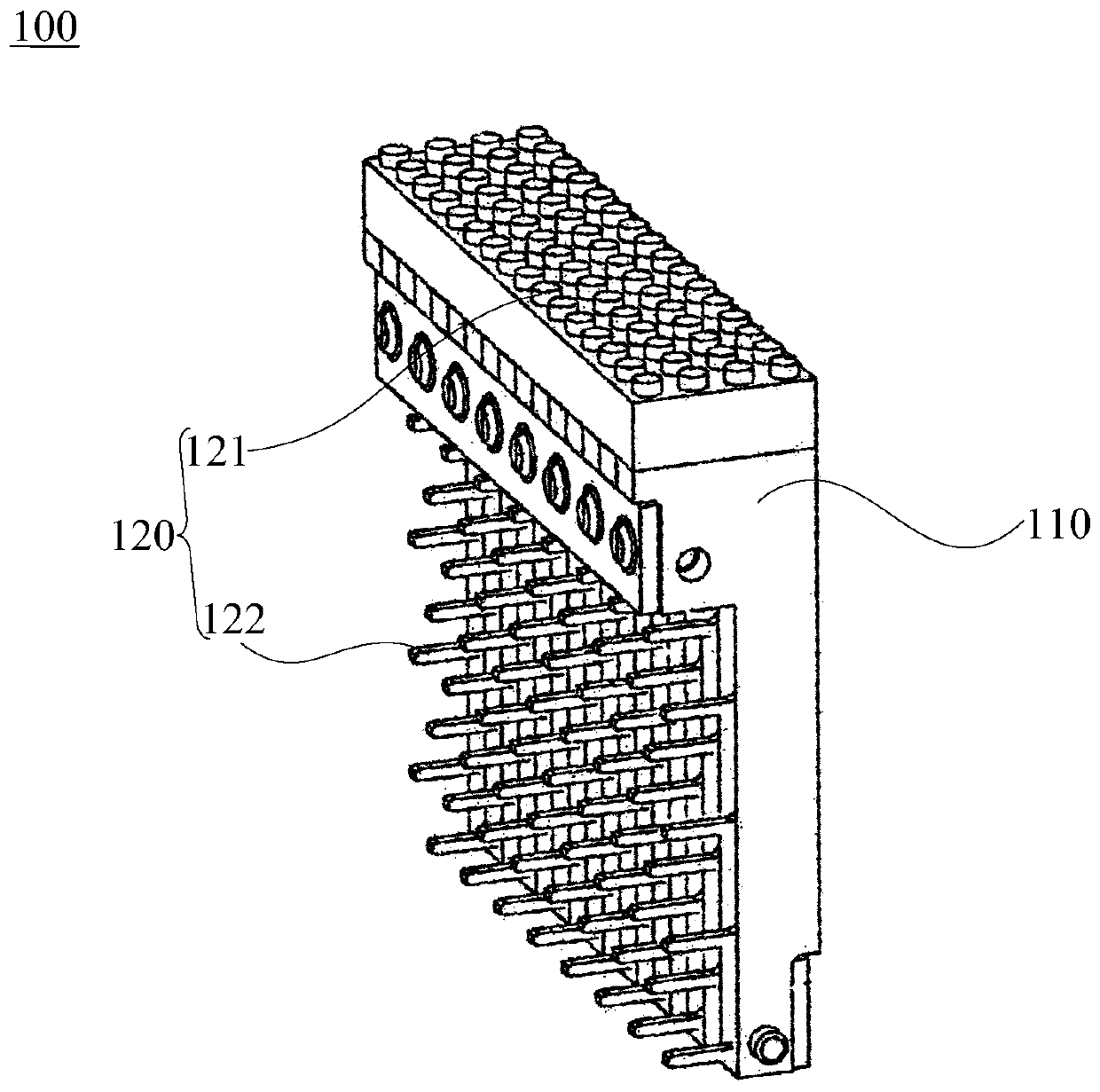
A welding method and auxiliary welding technology, applied in the direction of connection, circuit/collector parts, electrical components, etc., can solve the problems of inability to test PCBA connectors, false test tests, unqualified tests, etc.

Active Publication Date: 2019-09-06
SHENZHEN MASONE ELECTRONICS
View PDF6 Cites 0 Cited by
  • Summary
  • Abstract
  • Description
  • Claims
  • Application Information

AI Technical Summary

Problems solved by technology

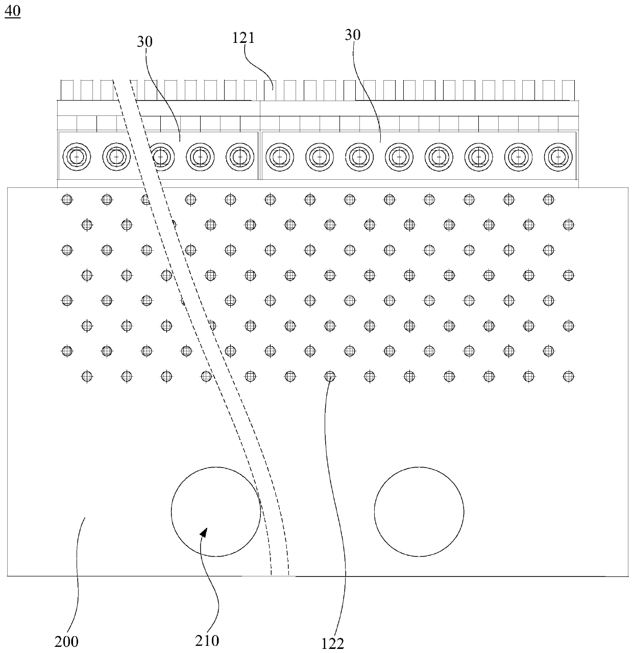
[0003] However, during the soldering process, the connector usually warps, causing the terminal array to deform. After multiple PCBA connectors are assembled, the deformation of the large-area terminal array will be more obvious. The pogo pin array on the test bed and the large After the area terminal array is in contact, it will be misaligned and open circuit will occur, which will make it impossible to test the PCBA connector, or, a wrong test will result in a failed test result.

Method used


Image

  • Welding method and auxiliary welding jig for pcba connector
  • Welding method and auxiliary welding jig for pcba connector
  • Welding method and auxiliary welding jig for pcba connector

Examples


Embodiment Construction

[0031] In order to facilitate the understanding of the present invention, the present invention will be described more fully below with reference to the associated drawings. Preferred embodiments of the invention are shown in the accompanying drawings. However, the present invention can be embodied in many different forms and is not limited to the embodiments described herein. On the contrary, the purpose of providing these embodiments is to make the disclosure of the present invention more thorough and comprehensive.

[0032] It should be noted that when an element is referred to as being “fixed” to another element, it can be directly on the other element or there can also be an intervening element. When an element is referred to as being "connected to" another element, it can be directly connected to the other element or intervening elements may also be present. The terms "vertical," "horizontal," "left," "right," and similar expressions are used herein for purposes of ill...


PUM


Abstract

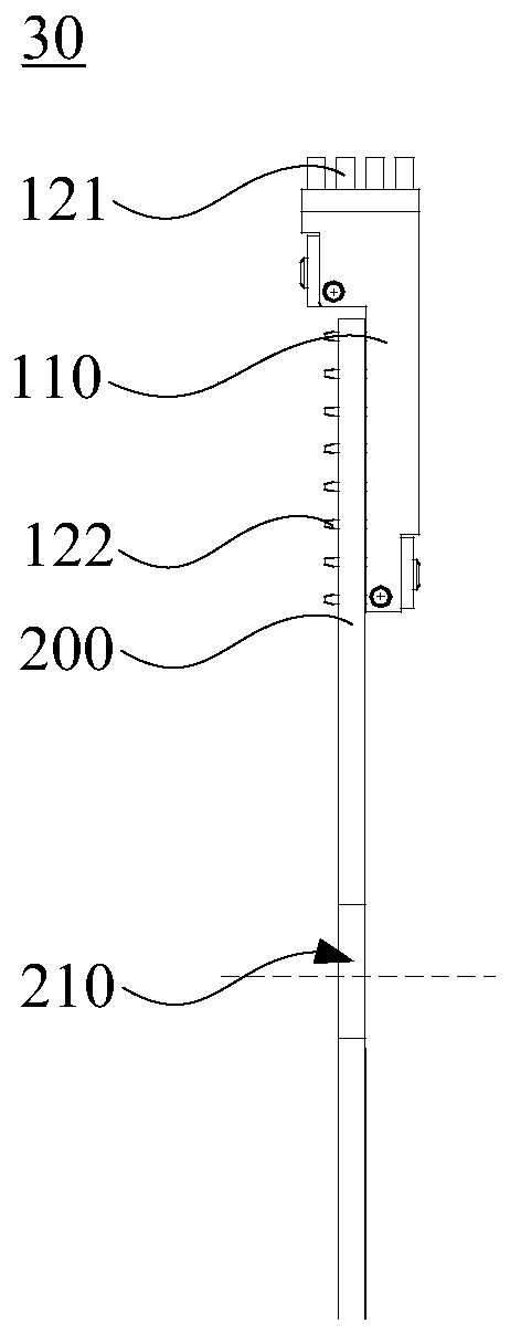
The invention relates to a PCBA connector welding method and an auxiliary welding fixture. Two PCBA connector groups to be welded are connected by the auxiliary welding fixture composed of a first connecting member, a second connecting member and a positioning member. The PCBA connector welding method is used to weld each PCBA connector to be welded in two PCBA connector groups to be welded, so that a number of PCBA connectors to be welded interact with each other to offset deformation caused by welding. The deformation of a large-area terminal array acquired after the assembly of a number ofPCBA connectors is avoided. The orderliness of welded terminal arrays in the PCBA connectors is effectively guaranteed, which facilitates accurate testing of a number of PCBA connectors. The auxiliarywelding fixture is used to connect a number of PCBA connectors to be welded together. A number of welded PCBA connectors are welded at the same time, which improves the welding efficiency.

Description

technical field [0001] The invention relates to the field of welding technology, in particular to a welding method of a PCBA connector and an auxiliary welding jig. Background technique [0002] The PCBA connector is obtained by soldering a PCBA electronic card and a connector with terminals arranged in an array. The soldered PCBA connector needs to be tested to ensure that it can be used normally. The conventional test method is to assemble multiple PCBA connectors together to form a large-area terminal array, and to align and match the pogo pin array on the test needle bed with the large-area terminal array one by one. Bed connection to test multiple PCBA connectors at the same time to improve test efficiency. [0003] However, during the soldering process, the connector usually warps, causing the terminal array to deform. After multiple PCBA connectors are assembled, the deformation of the large-area terminal array will be more obvious. The pogo pin array on the test be...

Claims


Application Information

Patent Timeline
Patent Type & Authority Patents(China)
IPC IPC(8): H01R43/02
Inventor 李新学高云峰
Owner SHENZHEN MASONE ELECTRONICS
Learn More