Eureka AIR delivers breakthrough ideas for toughest innovation challenges, trusted by R&D personnel around the world.

An electronic device and its rotating shaft mechanism

A technology of rotating shafts and rotating shafts, which is applied in the direction of electrical equipment shells/cabinets/drawers, electrical components, casings/cabinets/drawer components, etc., which can solve flexible screen damage, flexible screen bending, and affect the service life of flexible screens And other issues

Active Publication Date: 2020-03-24
LENOVO (BEIJING) LTD
View PDF6 Cites 0 Cited by
  • Summary
  • Abstract
  • Description
  • Claims
  • Application Information

AI Technical Summary

Problems solved by technology

[0003] However, the neutral layer of the existing shaft mechanism (neutral layer refers to a purely curved surface with no tension or compression inside when the thin plate is bent, for example, when a thick rubber plate is bent, the inner surface is compressed and the outer surface is stretched, between the inner surface and the inner surface. A surface layer between the surface and the outer surface is neither stretched nor compressed, it only bends, then this surface layer is the neutral layer) is located inside the rotating shaft mechanism, which is far away from the surface of the rotating shaft mechanism The neutral layer of the flexible screen, because there is a large distance between the two neutral layers, so when the rotating shaft mechanism makes the two parts of the electronic device rotate relative to each other, not only will the flexible screen laid on the outside of the rotating shaft mechanism Bending, and it will also make the flexible screen be stretched or compressed under tensile stress or compressive stress, resulting in damage to the flexible screen and affecting the service life of the flexible screen

Method used


Image

  • An electronic device and its rotating shaft mechanism
  • An electronic device and its rotating shaft mechanism
  • An electronic device and its rotating shaft mechanism

Examples


Embodiment Construction

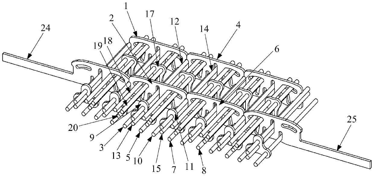
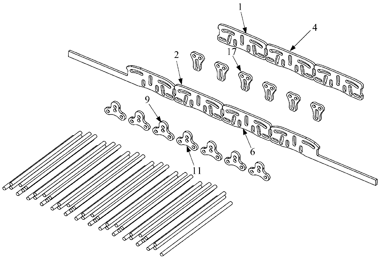
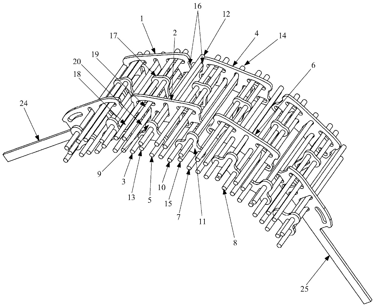
[0056] The invention provides a rotating shaft mechanism, which can make the neutral layer separate from itself and get closer to the neutral layer of the flexible screen, thereby reducing or even avoiding damage to the flexible screen and prolonging the service life of the flexible screen.

[0057] The following will clearly and completely describe the technical solutions in the embodiments of the present invention with reference to the accompanying drawings in the embodiments of the present invention. Obviously, the described embodiments are only some, not all, embodiments of the present invention. Based on the embodiments of the present invention, all other embodiments obtained by persons of ordinary skill in the art without making creative efforts belong to the protection scope of the present invention.

[0058] Such as Figure 1-Figure 14 As shown, the rotating shaft mechanism provided by the embodiment of the present invention is used to connect the first part and the se...


PUM


Abstract

The invention discloses a rotating shaft mechanism, and the rotating shaft mechanism comprises a plurality of connection units which are connected sequentially. Each connection unit comprises a firstconnecting part and a second connecting part; a first rotating shaft passing through the first connecting part and the second connecting part; a third connecting part; a second rotating shaft passingthrough the second connecting part and the third connecting part; a fourth connecting part; a third rotating shaft passing through the third connecting part and the fourth connecting part; a fourth rotating shaft passing through the fourth connecting part, wherein all rotating shafts are parallel to each other, and through holes which are disposed on all connecting parts and respectively allow thecorresponding rotating shafts to pass through are strip-shaped holes. According to the rotating shaft mechanism, because the rotating shafts are disposed in the strip-shaped holes, the rotating shafts can move and rotate, thereby achieving the uniform extending of the connection units, enabling a neutral layer of the rotating shaft mechanism to be transferred to the surface of a bent inner side to be closer to the neutral layer of a flexible curtain at the inner side of the rotating shaft mechanism, and reducing the damages to the flexible curtain. The invention also provides an electronic equipment with the above rotating shaft mechanism.

Description

technical field [0001] The present invention relates to the technical field of electronic equipment, in particular to a rotating shaft mechanism, and also relates to an electronic device having the above rotating shaft mechanism. Background technique [0002] At present, in order to further improve the working performance of electronic equipment, some electronic equipment is provided with flexible screens, and the two sides of the flexible screen are respectively connected to two parts of the electronic equipment that can rotate relatively, thereby increasing the display size as much as possible. area. Since the two parts of the electronic device that can rotate relative to each other are connected by a rotating shaft mechanism, the flexible screen needs to be covered on the rotating shaft mechanism. [0003] However, the neutral layer of the existing shaft mechanism (neutral layer refers to a purely curved surface with no tension or compression inside when the thin plate i...

Claims


Application Information

Patent Timeline
Patent Type & Authority Patents(China)
IPC IPC(8): H05K5/02
CPCH05K5/0226
Inventor 范小利杨润
Owner LENOVO (BEIJING) LTD
Why Eureka
Eureka Blog
Learn More