

Double-gun double-wire welding device and method
A welding gun and welding bracket technology, applied in the field of double-gun double-wire welding devices, can solve the problems of high equipment cost, high cost, large floor space, etc. Effect
- Summary
- Abstract
- Description
- Claims
- Application Information
AI Technical Summary
Problems solved by technology
Method used
Image

Examples
Embodiment 1
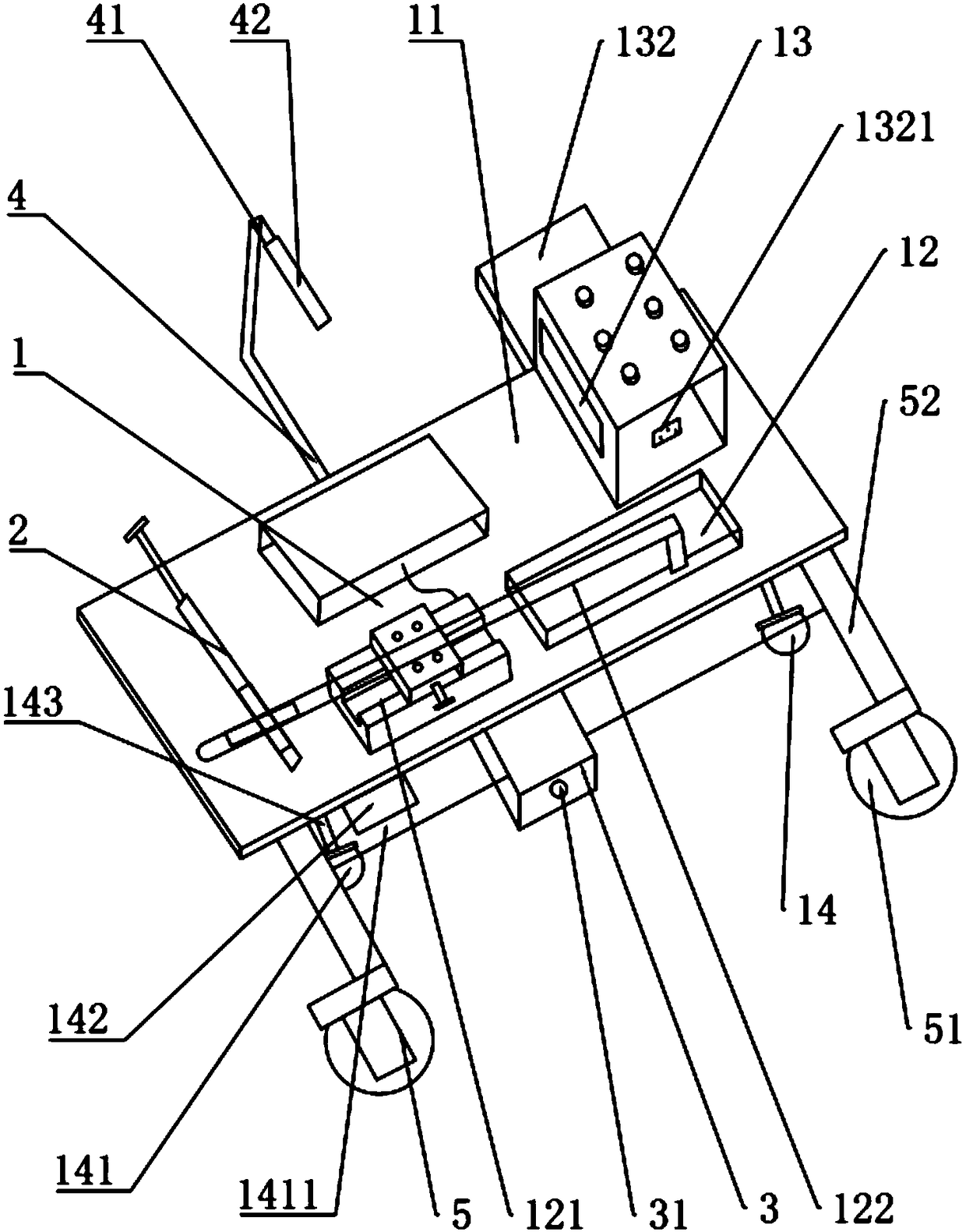
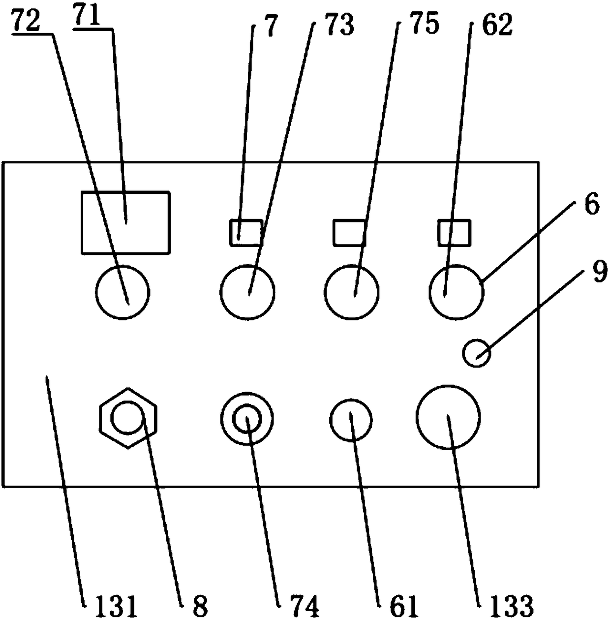
[0048] Such as Figure 1-2 As shown, the present invention provides a double-gun double-wire welding device, including: a welding module 1, two welding modules 1 are provided, the welding modules 1 are respectively arranged on two opposite sides of the workpiece to be welded, and the two welding modules 1 Corresponding setting; Welding module 1 comprises welding support 11, welding torch clamping mechanism 12, control mechanism 13 and moving mechanism 14, and the top of welding support 11 is provided with welding torch clamping mechanism 12 and control mechanism 13, and the rear end of welding torch clamping mechanism 12 A control mechanism 13 is provided, and the lower part of the welding bracket 11 is provided with a moving mechanism 14;
[0049] Mainly, the welding trolley is electromagnetically adsorbed on the platform, the front welding torch clamping mechanism 12 clamps the welding torch, and the guide wheel 51 sticks to the workpiece. Using its automatic tracking weldin...
Embodiment 2
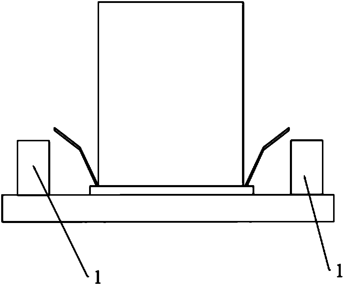
[0071] Such as Figure 3-4 Shown, utilize the welding method that the welding device of embodiment one realizes, comprise the steps:
[0072] S1. Fix the workpiece to be welded on the pedestal of the welding platform, and bring the welding seams on both sides of the workpiece to be welded close to the pedestal;
[0073] S2. Select a magnetic rail at a suitable position, and ride the two welding modules on the magnetic rail respectively, and make the magnetic fixing seat correspond to the magnetic rail;
[0074] S3, turn on the second switch, the magnetic fixing base is magnetized, the magnetic fixing base and the magnetic rail generate a magnetic adsorption force, and stabilize the welding module on the welding platform;
[0075] S4. Adjust the welding torch head of the welding torch to align it with the welding seam;
[0076] S5. Start the welding module, and at the same time that the welding module advances, the welding seams on both sides of the workpiece to be welded are...
PUM
 Abstract
Description
Claims
Application Information