Children seat and electric leg supporting mechanism thereof

A technology for child seats and leg rests, applied in child seats, child chairs, children's furniture, etc., can solve the problems of insufficient contact area, poor seat cushion riding experience, reduced safety, etc., to achieve easy operation and satisfactory comfort effect of enhancing safety

Pending Publication Date: 2018-06-15
SHANGHAI WOYOO ELECTRONIC TECHNOLOGY CO LTD
0 Cites 2 Cited by

AI-Extracted Technical Summary

Problems solved by technology

[0005] The purpose of the present invention is to overcome the defects of the prior art, provide a child seat and its electric leg support mechanism, and solve the...

Method used

As another preferred embodiment of the present invention, leg supporting board 21 comprises two side supporting boards 213 that are oppositely arranged, the top supporting board 214 that is connected at two side supporting boards 213 tops and is connected with two side supporting boards The front supporting plate 215 connected to the front portion of the plate 213 and the top supporting plate 214 is an arc-shaped plate. When the leg support plate 21 was installed in the cushion frame 11, the outer surface of the front support plate 215 was flush with the front end surfaces of the two side plates 111 of the seat cushion frame 11, and the slide bar 24 connected to the leg support plate 21 was positioned at the bottom of the chute 23. At the rear end, the connecting rod 25 is located at the rear end of the guide groove 26 . The two side support plates 213 of the leg support plate 21 are arranged adjacent to the corresponding side plates 111 on the cushion frame 11, and the side support plates 213 are located on the inner side of the side plates 111, and the side support plates 213 are realized by the slide bar 24 and the chute 23. And the connection of side plate 111. The top surface of the top support plate 214 is flush with the top surface of the side plate 111 . By designing the front support plate as an arc-shaped plate, the leg support plate 21 has better comfort.
As shown in Figure 1 and Figure 2, the present invention also provides a kind of child seat, and this child seat comprises cushion framework 11, and cushion framework 11 has opposite front side and rear side, and cushion framework 11 comprises oppositely arranged The two side plates 111 and the base plate 112 connecting the two side plates 111 are connected with the back frame 12 at the rear side of the two side plates 111, and the seat frame is formed by connecting the cushion frame 11 and the back frame 12. An electric leg rest mechanism 20 is installed on the front side of the two side plates 111. The electric leg rest mechanism 20 can be telescopically adjusted along the side plates 111. By adjusting the position of the electric leg rest mechanism 20, the...

Abstract

The invention relates to a children seat and an electric leg supporting mechanism thereof. The mechanism comprises a leg supporting plate slidably installed on a seat cushion framework and a driving structure in driving connection with the leg supporting plate, and the leg supporting plate can slidably stretch out of the front end of the seat cushion framework; the driving structure is installed on the seat cushion framework and drives the leg supporting plate to move back and forth along the seat cushion framework. By means of the electric leg supporting mechanism, when the length of a seat cushion is not enough, the slidable leg supporting plate can adjust the length of the seat cushion and stretch out of the front end of the seat cushion framework, the length of the seat cushion can beincreased, thus requirements of a children passenger for comfort can be met, and the safety can also be improved; the driving structure drives the leg supporting plate to slide, the operation is simple, the adjusting precision is high, the driving structure is depended on to lock the position of the leg supporting plate, and the children seat is safe and convenient to use.

Application Domain

Technology Topic

Image

  • Children seat and electric leg supporting mechanism thereof
  • Children seat and electric leg supporting mechanism thereof

Examples

  • Experimental program(1)

Example Embodiment

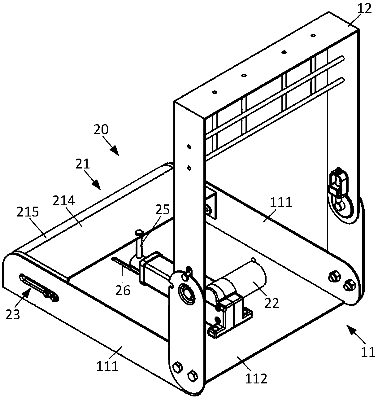
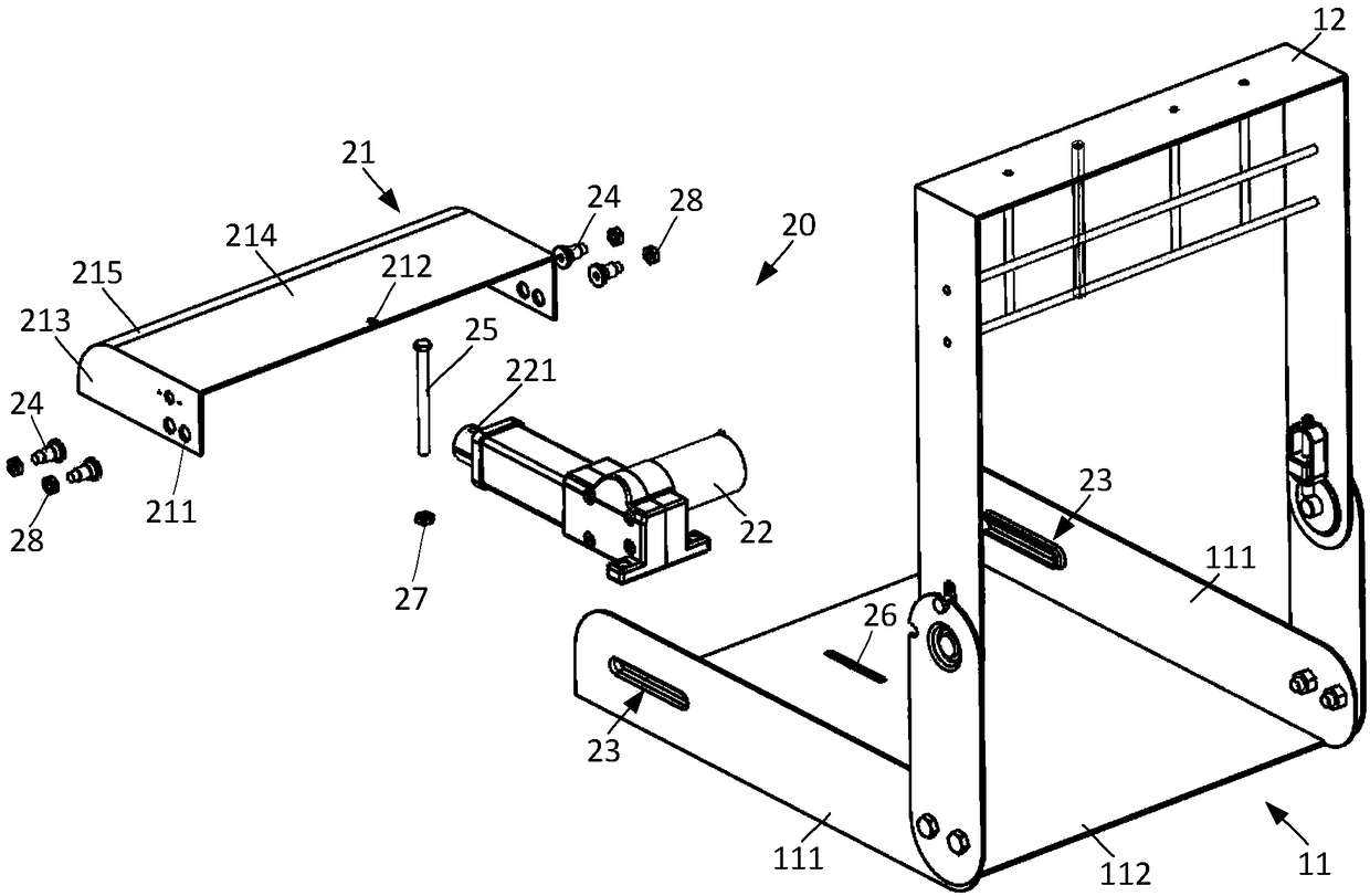
[0027] The present invention will be further described below in conjunction with the drawings and specific embodiments.
[0028] Refer to figure 1 , The present invention provides a child seat and its electric leg rest mechanism, which utilizes the sliding adjustment of the leg rest mechanism to achieve the purpose of adjusting the length of the seat cushion, and solves the problem that the existing seat cushion length cannot meet the riding needs of children with long legs. On the one hand, the riding experience is poor, and on the other hand, the cushioning contact area of ​​the cushion cannot reach the maximum range, which makes the safety in a collision accident lower. The leg support mechanism of the present invention can not only meet the comfort requirements of the child occupants, but also improve the safety of the child seat. The leg support mechanism is driven to slide by the driving structure, and the position of the leg support plate is locked by leaning on the driving structure, which is safe and convenient. The child seat and its electric leg rest mechanism of the present invention will be described below with reference to the accompanying drawings.
[0029] Refer to figure 1 , Shows a schematic diagram of the structure of the cushion frame and the electric leg support mechanism of the child seat of the present invention. Refer to figure 2 ,shown figure 1 Schematic diagram of the explosion decomposition structure. Combine below figure 1 with figure 2 The electric leg rest mechanism of the child seat of the present invention will be described.
[0030] Such as figure 1 with figure 2 As shown, the electric leg support mechanism 20 of the child seat of the present invention includes a leg support 21 and a driving structure 22. The leg support 21 is slidably mounted on the cushion frame 11, and the leg support 21 can slidably extend out of the cushion The front end of the frame 11 uses the extended leg support 21 to achieve the purpose of adjusting the length of the cushion; the driving structure 22 drives the connecting leg support 21, the driving structure 22 is installed on the cushion frame 11, and the leg support is driven by the driving structure 22 The board 21 moves back and forth along the cushion frame 11.
[0031] The front side of the seat cushion frame 11 is provided with a leg support 21 that can slide along the seat frame 11. By adjusting the position of the leg support 21, the length of the seat cushion can be increased to adapt to the leg length of the child occupant. Comfort, on the other hand, the leg support plate 21 increases the cushioning contact area, which can improve the safety of the child seat in a collision accident and ensure the safety of the child occupants.
[0032] As a preferred embodiment of the present invention, the two side plates 111 of the cushion frame 11 are provided with opposite sliding grooves 23, which are located in front of the side plate 111 of the cushion frame 11 and along the side plate of the cushion frame 11. 111 length direction setting;
[0033] The leg support 21 is placed between the two side plates 111 of the cushion frame 11, and both sides of the leg support 21 are provided with sliding rods 24 slidably arranged in the corresponding sliding grooves 23, and the sliding rods 24 are slidably arranged on the corresponding The sliding groove 23 allows the leg support 21 to slide along the sliding groove 23 for position adjustment.
[0034] Through the cooperation of the sliding groove 23 and the sliding rod 24, the leg support 21 is slidably arranged on the cushion frame 11, and the two side plates 111 are provided with sliding grooves 23, which can ensure that the leg support 21 is in the two sliding grooves 23 Sliding without flipping. The setting of the sliding groove 23 not only installs the leg support 21 on the cushion frame 11, but also provides a guiding function for the leg support 21 so that the sliding of the leg support 21 can only move along the sliding groove 23.
[0035] Further, a through hole 211 is opened on the side of the leg support plate 21 at a position corresponding to the sliding groove 23, and the sliding rod 24 passes through the through hole 211 and the sliding groove 23 and is screwed to connect a connecting nut 27, thereby connecting the leg support The board 21 and the side board 111 of the cushion frame 11. Preferably, the sliding rod 24 is a stepped bolt with bolts of different diameters. The middle bolt is placed in the sliding groove 23, and the sliding of the leg support plate 21 is realized by the middle bolt moving along the sliding groove 23 , The bolt located outside the sliding groove 23 is screwed to the connecting nut 27, and the bolt located inside the sliding groove 23 abuts against the inner surface of the side of the leg support plate 21.
[0036] As another preferred embodiment of the present invention, a through hole 221 is opened at the front end of the driving structure 22, and a connecting hole 212 is opened at the rear end of the leg support plate 21 at a position corresponding to the through hole 221. The hole 212 and the through hole 221 are screwed to connect a nut 27 to fasten the driving structure 22 and the leg support plate 21. The driving structure 22 and the leg support 21 are connected by the connecting rod 25, and the driving structure 22 drives the leg support 21 to slide back and forth along the cushion frame 11. When driving adjustment, the leg support 21 is pushed forward by the driving structure 22, so that the leg support 21 moves forward and protrudes from the front end of the cushion frame 11. The protruding length is controlled by the driving structure 22. When the requirement is met, the operation of the driving structure 22 can be stopped, thereby stopping the movement of the leg support plate 21. If it is necessary to retract the leg support plate 21 into the cushion frame 11, the driving structure 22 pulls the leg support plate 21 backward, so that the leg support plate 21 moves backward and is recovered into the cushion frame 11, and the driving structure 22 is recovered in place Stop running.
[0037] Further, in order to ensure the stability of the movement process of the driving structure 22 driving the leg support 21, the bottom plate 113 of the seat cushion frame 11 is provided with a guide groove 26 corresponding to the connecting rod 25, and the guide groove 26 is arranged along the length direction of the seat cushion frame 11. That is, the setting direction of the guide groove 26 is the same as the setting direction of the sliding groove 23; the end of the connecting rod 25 is passed through the guide groove 26 and then the connecting nut 27 is screwed, and the connecting rod 25 is guided through the guide groove 26. When the driving structure 22 drives the leg support 21 through the connecting rod 25, the connecting rod 25 moves back and forth in the guide groove 26, and the guide groove 26 plays a role of guiding and limiting the connecting rod 25. Thus, the stability of the driving structure 22 when driving the leg support plate 21 to move is improved. Preferably, the connecting rod 25 is a long bolt. Specifically, the end of the long bolt passes through the connecting hole 212 on the leg support plate 21, passes through the through hole 221 at the front end of the driving structure 22, and then passes through the guide groove. 26. It is screwed and connected with a nut 27. A certain gap is left between the nut 27 and the bottom surface of the bottom plate 112 of the cushion frame 11, so that the long bolt can move back and forth in the guide groove 26. Preferably, the length of the guide groove 26 is set to match the adjustment length of the leg support plate 21, so that the guide groove 26 can meet the length adjustment requirements of the leg support plate 21.
[0038] As another preferred embodiment of the present invention, the driving structure 22 is installed on the bottom plate 112 of the cushion frame 22. Preferably, the driving structure 22 is a push rod motor. The front end of the push rod motor is a retractable push rod, and a through hole 221 is provided at the end of the push rod to connect the connecting rod 25, so that the movement of the leg support plate 21 is driven by the retractable push rod. The control button of the push rod motor is arranged on the child seat to facilitate the user to adjust. The control button includes a first button to control the forward rotation of the push rod motor and a second button to control the reverse rotation of the push rod motor. The first button causes the push rod motor to rotate forward to drive the leg support to move forward from the front end of the cushion frame. After moving to the position, release the first button, the push rod motor stops running and locks the position of the leg support; Moving the second button causes the push rod motor to reversely drive the leg support to move backward and retract into the cushion frame. After moving to the position, release the second button, the push rod motor stops running and locks the position of the leg support.
[0039] As yet another preferred embodiment of the present invention, the leg support plate 21 includes two opposite side support plates 213, a top support plate 214 connected to the top of the two side support plates 213, and a front support plate connected to the two side support plates 213. The front support plate 215 is connected to the top support plate 214, and the front support plate 215 is an arc-shaped plate. When the leg support plate 21 is installed in the cushion frame 11, the outer surface of the front support plate 215 is flush with the front end faces of the side plates 111 of the cushion frame 11, and the slide bar 24 connected to the leg support plate 21 is located in the slide groove 23 at this time. At the rear end, the connecting rod 25 is located at the rear end of the guide groove 26. The two side support plates 213 of the leg support plate 21 are attached to the corresponding side plates 111 on the cushion frame 11, and the side support plates 213 are located inside the side plates 111, and the side support plates 213 are realized by the sliding rod 24 and the sliding groove 23 And the connection of the side plate 111. The top surface of the top support plate 214 is flush with the top surface of the side plate 111. By designing the front support plate as an arc-shaped plate, the leg support plate 21 has better comfort.
[0040] The following describes the child seat provided by the present invention.
[0041] Such as figure 1 with figure 2 As shown, the present invention also provides a child seat, the child seat includes a cushion frame 11, the cushion frame 11 has opposite front and rear sides, the cushion frame 11 includes two opposite side panels 111 and two connecting The bottom plate 112 of each side plate 111 is connected with a backrest frame 12 on the rear side of the two side plates 111, and a seat frame is formed by connecting the cushion frame 11 and the backrest frame 12. An electric leg support mechanism 20 is installed on the front side of the two side plates 111. The electric leg support mechanism 20 can be telescopically adjusted along the side plates 111. By adjusting the position of the electric leg support mechanism 20, the length of the seat cushion can be increased to adapt to The long legs of the child occupant improve the comfort of the child occupant on the one hand, and on the other hand the leg support plate 21 increases the cushioning contact area, which can improve the safety of the child seat in a collision accident and ensure the safety of the child occupant. The specific structure of the electric leg rest mechanism 20 in the child seat of the present invention is the same as the structure of the above-mentioned child seat electric leg rest mechanism. For details, please refer to the description of the above structure, and will not be repeated here.
[0042] The present invention has been described in detail above in conjunction with the embodiments of the drawings, and those of ordinary skill in the art can make various changes to the present invention based on the above description. Therefore, some details in the embodiments should not constitute a limitation to the present invention, and the present invention will take the scope defined by the appended claims as the protection scope of the present invention.

PUM

no PUM

Description & Claims & Application Information

We can also present the details of the Description, Claims and Application information to help users get a comprehensive understanding of the technical details of the patent, such as background art, summary of invention, brief description of drawings, description of embodiments, and other original content. On the other hand, users can also determine the specific scope of protection of the technology through the list of claims; as well as understand the changes in the life cycle of the technology with the presentation of the patent timeline. Login to view more.

Similar technology patents

Preparation method of comfortable copying pen holder

ActiveCN110774516AMeet comfortHigh mechanical strengthCoatingsHigh-density polyethyleneEthylene-propylene-diene-monomer
Owner:QIQIHAR UNIVERSITY

Active participation type spine correction instrument

ActiveCN111530028AMeet comfortEffective exerciseGymnastic exercisingMedical scienceMuscle strengthBack+Spine
Owner:BEIJING JISHUITAN HOSPITAL

Cold protective clothing with heating devices and manufacturing method of cold protective clothing

PendingCN109512051AImprove cold and heat preservation abilityMeet comfortGarment special featuresProtective garmentEngineeringPhysiological responses
Owner:JILIN ELECTRIC POWER RES INST +2

Leg support mechanism for gait training rehabilitation robot

PendingCN109846668AAchieve adjustabilityMeet comfortChiropractic devicesWalking aidsGait trainingEngineering
Owner:GUANGXI UNIV

Regenerated spinning raw material turnover skip car

InactiveCN103144661AMeet comfortEasy to operateHand carts with multiple axesHandrailPlugboard
Owner:扬州天富龙集团股份有限公司

Classification and recommendation of technical efficacy words

  • Improve security
  • Meet comfort

Stepless adjusting device applicable to lengths of four limbs of rehabilitation robot

PendingCN107361996AEfficient regulationMeet comfortGymnastic exercisingChiropractic devicesEngineeringBevel gear
Owner:合肥哈工力训智能科技有限公司

Energy-absorbing soft base of engine

InactiveCN102705416ASatisfy securityMeet comfortShock absorbersEnergy absorbingEngineering
Owner:CHANGZHOUASIAN ENDERGONIC ELECTRONICS TECH CO LTD
Why Eureka
Try Eureka