Stepless adjusting device applicable to lengths of four limbs of rehabilitation robot

A rehabilitation robot and stepless adjustment technology, applied in the direction of passive exercise equipment, manipulators, gymnastics equipment, etc., can solve the problems of adding product accessories, existing alignment, reducing operation efficiency, etc., and achieve the effect of satisfying comfort and fast and efficient adjustment

Pending Publication Date: 2017-11-21
合肥哈工力训智能科技有限公司
6 Cites 14 Cited by

AI-Extracted Technical Summary

Problems solved by technology

[0004] Fixed mechanical limbs are roughly divided into different lengths of mechanical limbs based on different people. There are disadvantages: the length of fixed mechanical limbs cannot meet the use requirements of people of different heights in a small range, and the addition of product accessories
[0005] Equidistant hole length adjustment is to open a number of equidistant threads or light ho...

Method used

3. adopt bevel gear pair 90 ° to turn and trapezoidal screw pair to be the main shaft system form, rationally utilize bar internal space, and the rotary knurling handle is output on the outside, easy to operate; If there is electric control needs, taper A motor can be connected to the outside of the gear shaft to realize electronically controlled automatic adjustment; the scope of protection also includes replacing the trapezoidal screw pair in this patent with other such as a ball screw pair;
4. Adopt the double guide rail insert and guide rail that are easy to disassemble, constitute T-shaped rectangular guide rail guide, convenient dismounting, compare complex V type, dovetail guide rail, reduce structural processing difficulty;
Bevel gear shafting comprises bevel gear shaft 5, two bevel gears 8, blocking cap 6, cover plate 4, bevel gear shaft deep groove ball bearing 7. One end of the bevel gear shaft 5 is installed in the groove, and the other end extends out of the fixed rod 2 and forms a rotating operation part. Two bevel gears 8 are installed in the groove, one of which is coaxially fixed with the bevel gear shaft 5 and driven to rotate by the bevel gear shaft 5, and the two bevel gears 8 mesh. The bevel gear shaft deep groove ball bearing 7 is matched with the bevel gear shaft 5 to reduce the friction coefficient when the bevel gear shaft 5 rotates. The bevel gear shaft deep groove ball bearing 7 is coaxially installed on the bevel gear shaft 5 and is located on the fixed rod 2 inside the outer wall. The cover plate 4 is installed on the end face of the deep groove ball bearing 7 of the bevel gear shaft. Blocking cap 6 is installed on the outer sidewall of fixed rod 2 and is used for shielding bevel gear shaft deep groove ball bearing 7. The cover plate 4 and the baffle cap 6 can be arranged one by one, can be arranged at the same time, or neither can be arranged, and are not necessary parts of the bevel gear shaft system.
Described bevel gear shaft system: based on bevel gear shaft 5, bevel gear 8 is fixedly set on it, both sides are respectively provided with bevel gear shaft side bearing cover plate 4, bevel gear shaft deep groove ball bearing 7, and The fixed rods 2 are connected to ensure the coaxiality of rotation.
Describe...

Abstract

The invention discloses a stepless adjusting device applicable to the lengths of four limbs of a rehabilitation robot. The stepless adjusting device comprises a fixed rod, a slide rod and a stepless adjusting mechanism. The stepless adjusting mechanism comprises a bevel gear shaft system and a lead screw pair transmission shaft system. The bevel gear shaft system comprises a bevel gear shaft and two meshing bevel gears. One end of each bevel gear is mounted in a groove, the other end of each bevel gear extends out of the fixed rod, and rotary operation portions are formed at the other ends of the bevel gears. One of the bevel gears is coaxially fixed to the bevel gear shaft and can be driven by the bevel gear shaft to rotate. The lead screw pair transmission shaft system comprises a lead screw shaft, a lead screw deep groove ball bearing and a nut. One end of the lead screw shaft is coaxially fixed to the other bevel gear, the other end of the lead screw shaft is screwed with the nut and extends into the slide rod via the nut. The lead screw deep groove ball bearing is matched with the lead screw shaft and is mounted between the inner side walls of the grooves and the lead screw shaft. Rotary force of the operation portions of the bevel gear shaft can be transmitted onto the lead screw shaft by the aid of meshing of the two bevel gears, and the nut can be ultimately driven to drive the slide rod to move relative to the fixed rod.

Application Domain

Technology Topic

Image

  • Stepless adjusting device applicable to lengths of four limbs of rehabilitation robot
  • Stepless adjusting device applicable to lengths of four limbs of rehabilitation robot
  • Stepless adjusting device applicable to lengths of four limbs of rehabilitation robot

Examples

  • Experimental program(1)

Example Embodiment

[0022] In order to make the objectives, technical solutions, and advantages of the present invention clearer, the following further describes the present invention in detail with reference to the accompanying drawings and embodiments. It should be understood that the specific embodiments described here are only used to explain the present invention, but not to limit the present invention.
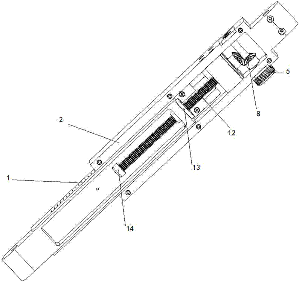
[0023] See figure 1 , The stepless adjustment device suitable for the limb length of the rehabilitation robot of the present invention mainly includes three parts: a fixed rod 2, a sliding rod 1, and a stepless adjustment mechanism. One end of the sliding rod 1 is embedded in the groove of the fixed rod 2 and can move along the length of the fixed rod 2. The infinite adjustment mechanism drives the sliding rod 1 relative to the fixed rod 2 to move along the length of the fixed rod 2.
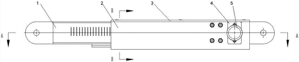
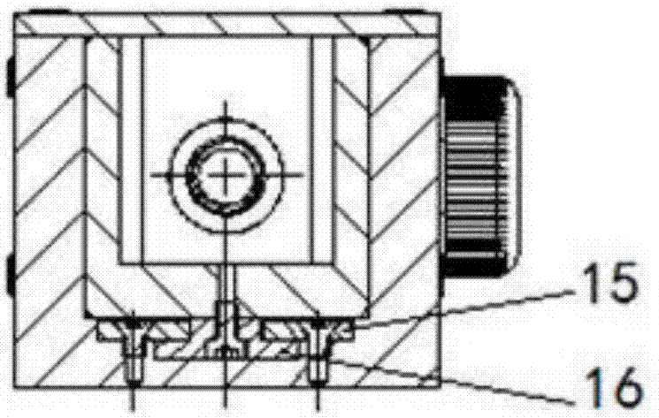
[0024] Please combine figure 2 , image 3 and Figure 4 , The stepless adjustment mechanism mainly includes two parts: a bevel gear shaft system and a lead screw drive shaft system.
[0025] The bevel gear shaft system includes a bevel gear shaft 5, two bevel gears 8, a stop cap 6, a cover plate 4, and a bevel gear shaft deep groove ball bearing 7. One end of the bevel gear shaft 5 is installed in the groove, and the other end extends out of the fixed rod 2 and forms a rotating operation part. Two bevel gears 8 are installed in the groove, one of the bevel gears 8 is coaxially fixed with the bevel gear shaft 5 and driven to rotate by the bevel gear shaft 5, and the two bevel gears 8 mesh. The bevel gear shaft deep groove ball bearing 7 is matched with the bevel gear shaft 5 to reduce the coefficient of friction when the bevel gear shaft 5 rotates. The bevel gear shaft deep groove ball bearing 7 is coaxially mounted on the bevel gear shaft 5 and located on the fixed rod 2. Inside the outer wall. The cover plate 4 is installed on the end surface of the bevel gear shaft deep groove ball bearing 7. The blocking cap 6 is installed on the outer side wall of the fixed rod 2 to block the bevel gear shaft deep groove ball bearing 7. The cover plate 4 and the blocking cap 6 can be provided alternatively, or at the same time, or neither can be provided, and they are not a necessary part of the bevel gear shaft system.
[0026] The screw drive shaft system includes a screw shaft 12, a nut 13, a screw shaft deep groove ball bearing 11, a limit cap 14, a bearing seat 10, and an end cover 9. One end of the screw shaft 12 is coaxially fixed with another bevel gear 8. The screw shaft deep groove ball bearing 11 is matched with the screw shaft 12 and is installed between the inner wall of the groove and the screw shaft 12. The nut 13 is fixed on the sliding rod 1 and screwed with the other end of the screw shaft 12, and the other end of the screw shaft 12 extends into the sliding rod 1 via the nut 13. The limit cap 14 is fixed on one end of the screw shaft 12 that extends into the sliding rod 1 via the nut 13. The bearing seat 10 is used to install the screw shaft deep groove ball bearing 11, the bearing seat 10 is fixed on the inner side wall of the groove, and the end cover 9 is fixed on the end surface of the screw bearing seat 10 facing the bevel gear 8.
[0027] The rotational force of the operating part of the bevel gear shaft 5 is transmitted to the screw shaft 12 by the engagement of the two bevel gears 8, and finally the nut 13 is driven to drive the sliding rod 1 to move relative to the fixed rod 2. In order to improve the transmission stability of the screw shaft 12, the diameter of the section on the screw shaft 12 that is matched with the screw shaft deep groove ball bearing 11 is larger than the diameter of the section that is matched with the nut 13, and is also larger than that of the corresponding bevel gear 8. Segment diameter.
[0028] In order to improve the movement performance of the sliding rod 1, at least one guide rail 16 for guiding the movement of the sliding rod 1 is fixed on the side wall of the groove. The guide rail 16 is provided with a T-shaped chute, and the outer side wall of the sliding rod 1 is fixed T-shaped guide rail insert 15 matched with the chute.
[0029] The present invention uses a fixed rod 2 as a support. The sliding rod 1 is embedded in the fixed rod 2 and can move along the length of the fixed rod 2. Two co-planar transmission shaft systems are set on the center lines of the two rods, including a bevel gear shaft system and a lead screw pair transmission shaft system perpendicular to it. Rotate the bevel gear shaft 5 with knurled handle to make the two bevel gears 8 mesh and rotate Therefore, the 90° reversal causes the trapezoidal screw shaft 12 to rotate, and the screw shaft nut 13 drives the sliding rod 1 to move, so as to adjust the length of the joint opening between the two rods. The bottom of the two rods is provided with a T-shaped combined guide rail 16 and a T-shaped guide rail insert 15 to ensure relative sliding stability and parallel guidance.
[0030] The bevel gear shaft system: based on the bevel gear shaft 5, bevel gears 8 are fixed on it, and bevel gear shaft side bearing covers 4, bevel gear shaft deep groove ball bearings 7, and fixed rods 2 are set on both sides. Connect to ensure rotation coaxiality.
[0031] The screw drive shaft system is mainly composed of a trapezoidal screw shaft 12 and a screw shaft nut 13. The screw shaft nut 13 is fixed to the sliding rod 1, and the trapezoidal screw shaft 12 is used as a core part, which is set on the fixed rod. The trapezoidal screw bearing seat 10 on 2 is used as a support, and a pair of screw shaft deep groove ball bearings 11 and end caps 9 are provided for radial support and end surface limit, to ensure radial stability and no axial movement during the rotation process; A screw limit cap 14 is provided on the other side of the trapezoidal screw shaft 12 to limit the movement of the screw shaft nut 13 to ensure that the screw shaft nut 13 moves axially within a safe set stroke.
[0032] The combination of rail 16 and T-shaped rail insert 15 such as image 3 As shown in the left cross-sectional view, two T-shaped guide rail inserts 15 are arranged on the symmetrical two sides of the bottom of the fixed rod 2, and the T-shaped guide rail 16 is installed at the center of the bottom of the sliding rod 1. Of course, the guide rail 16 and the T-shaped guide rail insert 15 can also be installed in reverse. For example, at least one guide rail 16 for guiding the movement of the sliding rod 1 is fixed on the side wall of the groove, and the guide rail 16 is provided with a chute with a T-shaped cross section. The outer side wall of the sliding rod 1 is fixed with a T-shaped guide rail insert 15 matched with the sliding groove.
[0033] One side of the fixed rod 2 can be provided with a joint hinge hole, which is used to connect the joints of the limbs of the robot, and the fixed rod cover 3 is installed on the upper side, which is mainly dustproof and restricts the side of the sliding rod. The cross-sectional shape is U-shaped , Stepped steps are milled at the bottom for the installation of T-row rail pairs.
[0034] One side of the sliding rod 1 can also be provided with joint hinge holes, which are used to connect the joints of the limbs of the robot, and laser engraving scales are set on both sides, which can display the center distance of the joint holes of the two rods, which is convenient for the operator to adjust.
[0035] The operation process of the present invention is: the operator rotates the knurled handle on the side of the bevel gear shaft 5 counterclockwise or clockwise, and drives the sliding rod 2 to advance or retreat a distance relative to the fixed rod 1 through the bevel gear meshing transmission and the transmission of the screw pair. , Observe the indicator scale on the sliding rod 1 until it is adjusted to a suitable position, and the operation is complete.
[0036] Compared with the existing robot limb length adjustment technology, the invention has stepless adjustment of the limb length at any position within the size range, accurate and rapid positioning adjustment through scale guidance, structure transplantation and strong expandability, and is suitable for rehabilitation robots, exoskeleton robots, and other robots. The field of mechanical limb adjustment such as human robot field.
[0037] In summary, the key technology or extension technology of the present invention is as follows:
[0038] 1. Stepless length adjustment, instead of the original jack-type intermittent adjustment structure, can realize any length positioning within the adjustment range;
[0039] 2. Scope of application extension: the right features include this structure rehabilitation robot, exoskeleton robot hip-knee joint lower limb, lower limb lower leg between bare knee joints, upper limb upper arm between shoulder and elbow joints, and upper limb lower arm between elbow-wrist joints.
[0040] 3. The bevel gear pair 90° steering and the trapezoidal screw pair are adopted as the main shaft system form, the internal space of the rod is reasonably used, and the rotary knurled handle is output on the outside, which is convenient for operation; if electric control is required, the outside of the bevel gear shaft The motor can be connected to realize electronic control and automatic adjustment; the scope of protection also includes replacing the ladder-type screw pair in this patent with other such as ball screw pair;
[0041] 4. Adopting easy-to-disassemble double guide rails and guide rails to form a T-shaped rectangular guide rail, which is convenient for disassembly and assembly. Compared with complex V-shaped and dovetail guide rails, it reduces the difficulty of structural processing;
[0042] 5. Joint hinge holes are provided on both sides of the fixed rod and the sliding rod, which are used for the expansion connection of the joints of the robot's limbs; holes can be opened on the side to install other structures such as protective gear brackets and link hinges for fixed limbs;
[0043] 6. With laser marking, the operator can manually adjust to the appropriate length position according to the scale display; later, the sensor can be measured according to the length of the grating or magnetic scale, which can be upgraded to a real-time digital output display of length.
[0044] The above descriptions are only preferred embodiments of the present invention and are not intended to limit the present invention. Any modification, equivalent replacement and improvement made within the spirit and principle of the present invention shall be included in the protection of the present invention. Within range.

PUM

no PUM

Description & Claims & Application Information

We can also present the details of the Description, Claims and Application information to help users get a comprehensive understanding of the technical details of the patent, such as background art, summary of invention, brief description of drawings, description of embodiments, and other original content. On the other hand, users can also determine the specific scope of protection of the technology through the list of claims; as well as understand the changes in the life cycle of the technology with the presentation of the patent timeline. Login to view more.

Similar technology patents

Energy saving vehicle

InactiveCN104554511AEfficient regulationAvoid expending energyVehiclesNew energySteering wheel
Owner:XIAN JUNXIE OPTOELECTRONICS TECH

Active participation type spine correction instrument

ActiveCN111530028AMeet comfortEffective exerciseGymnastic exercisingMedical scienceMuscle strengthBack+Spine
Owner:BEIJING JISHUITAN HOSPITAL

Regenerated spinning raw material turnover skip car

InactiveCN103144661AMeet comfortEasy to operateHand carts with multiple axesHandrailPlugboard
Owner:扬州天富龙集团股份有限公司

Classification and recommendation of technical efficacy words

  • Meet comfort
  • Efficient regulation

Energy-absorbing soft base of engine

InactiveCN102705416ASatisfy securityMeet comfortShock absorbersEnergy absorbingEngineering
Owner:CHANGZHOUASIAN ENDERGONIC ELECTRONICS TECH CO LTD
Why Eureka
Try Eureka