A Fast Optical Correction Method

An optical calibration and fast technology, applied in the field of optical calibration, can solve problems such as laborious, time-consuming, and inability to guarantee calibration accuracy, and achieve the effect of great promotion value, convenient calibration, and reducing the probability of panel missed and wrong detection.

Active Publication Date: 2020-07-28
SUZHOU JINGLAI OPTO CO LTD
View PDF8 Cites 0 Cited by
  • Summary
  • Abstract
  • Description
  • Claims
  • Application Information

AI Technical Summary

Problems solved by technology

[0003] The purpose of the present invention is to solve the problems of time-consuming and labor-intensive calibration methods for multiple CCD cameras in the prior art mentioned in the background technology, and the calibration accuracy cannot be guaranteed, and to provide a fast optical calibration method

Method used


Image

  • A Fast Optical Correction Method
  • A Fast Optical Correction Method
  • A Fast Optical Correction Method

Examples


Embodiment Construction

[0027] The present invention will be further described in detail below in conjunction with the accompanying drawings and specific embodiments.

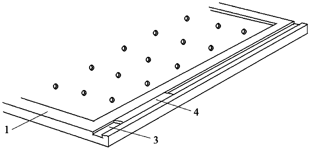
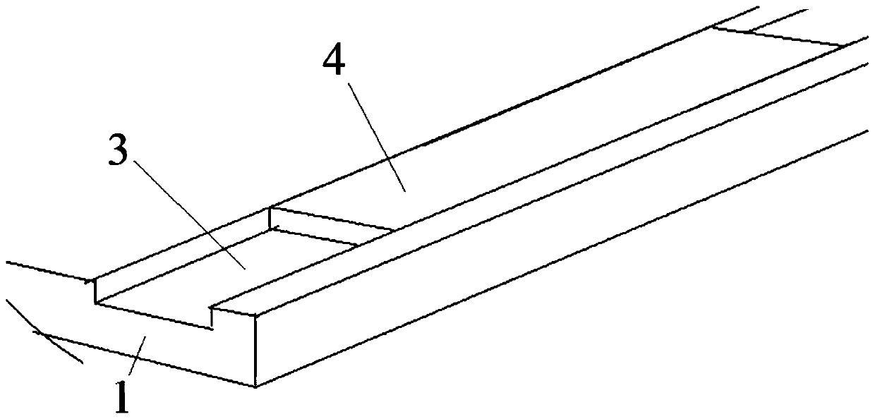
[0028] Such as Figure 1~4 , a fast optical calibration method, including a stage 1, the stage 1 is detachably mounted on a detection platform (carrying a test object) of a detection device. In this embodiment, a chute 3 arranged along the arrangement direction of a plurality of CCD cameras 2 is provided on the stage 1, the depth, straightness and flatness of the chute 3 are less than ±10 microns, and the chute 3 is a groove with an upper opening Slot structure, a correction plate 4 is placed in the chute 3 and can slide along the length direction of the chute 3, and the surface of the correction plate 4 is on the same plane as the surface of the detection platform. The correction plate 4 is a crystal glass substrate, and its length, width and height are 120 mm * 20 mm * 4.3 mm. The width of the correction plate 4 is about 100 micron...


PUM

PropertyMeasurementUnit
lengthaaaaaaaaaa
lengthaaaaaaaaaa

Abstract

The invention relates to the technical field of correction of optical light sources, in particular to a fast optical correction method. The fast optical correction method comprises the steps of: providing a calibration plate, wherein a plurality of first indications are arranged on the calibration plate, and the plurality of first indications are on a straight line; acquiring position informationof at least two first indications on the calibration plate by means of the first CCD camera among the plurality of CCD cameras in the arrangement direction thereof, acquiring position information of at least two another first indications on the calibration plate (4) by means of the second CCD camera, and adjusting the first CCD camera and the second CCD camera by utilizing the acquired position information so that the line of centers of the two CCD cameras is parallel to the connecting lines of the first indications; and sequentially adjusting the rest CCD cameras according to the fast opticalcorrection method. The fast optical correction method is convenient and fast in correction, can precisely adjust the CCD cameras and the light source to be precisely matched, improve the efficiency of panel detection, reduce the probability of panel missed detection and misdetection, has the extremely simple correction method, and has great popularization value.

Description

technical field [0001] The invention relates to the technical field of optical correction, in particular to a device for quickly correcting multiple optical cameras and light sources. Background technique [0002] Optical inspection is an important link in the panel production process. At present, with the rapid development of smart phones, the output of panels is increasing. It is necessary to greatly improve the efficiency of panel production and inspection to meet the growing demand. Usually, in order to improve the efficiency of panel inspection, the number of CCD cameras is increased, and the detection area per unit time is increased through a large number of CCD cameras, so as to improve the efficiency of panel inspection. However, the use of multiple CCD cameras will make the calibration of the CCD cameras face multiple difficulties. The existing adjustment method is to adjust the light source and angle of a single optical CCD camera with a calibration sheet or a cal...

Claims


Application Information

Patent Timeline
Patent Type & Authority Patents(China)
IPC IPC(8): G01N21/84G01N21/01
Inventor 杨慎东郭连俊颜圣佑
Owner SUZHOU JINGLAI OPTO CO LTD
Why Eureka
Try Eureka