Foldable cleaning device
A cleaning device and foldable technology, applied in transportation, packaging, escalators, etc., can solve problems such as slipping, hidden dangers, and safety, and achieve the effect of convenient use and effective cleaning
- Summary
- Abstract
- Description
- Claims
- Application Information
AI Technical Summary
Problems solved by technology
Method used
Image

Examples
Embodiment Construction
[0023] The present invention will be further described below in conjunction with the accompanying drawings.
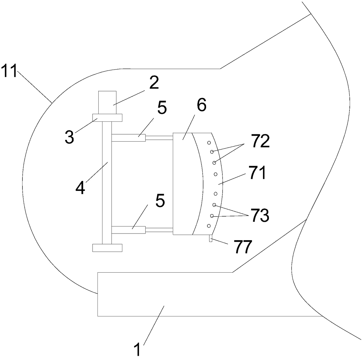
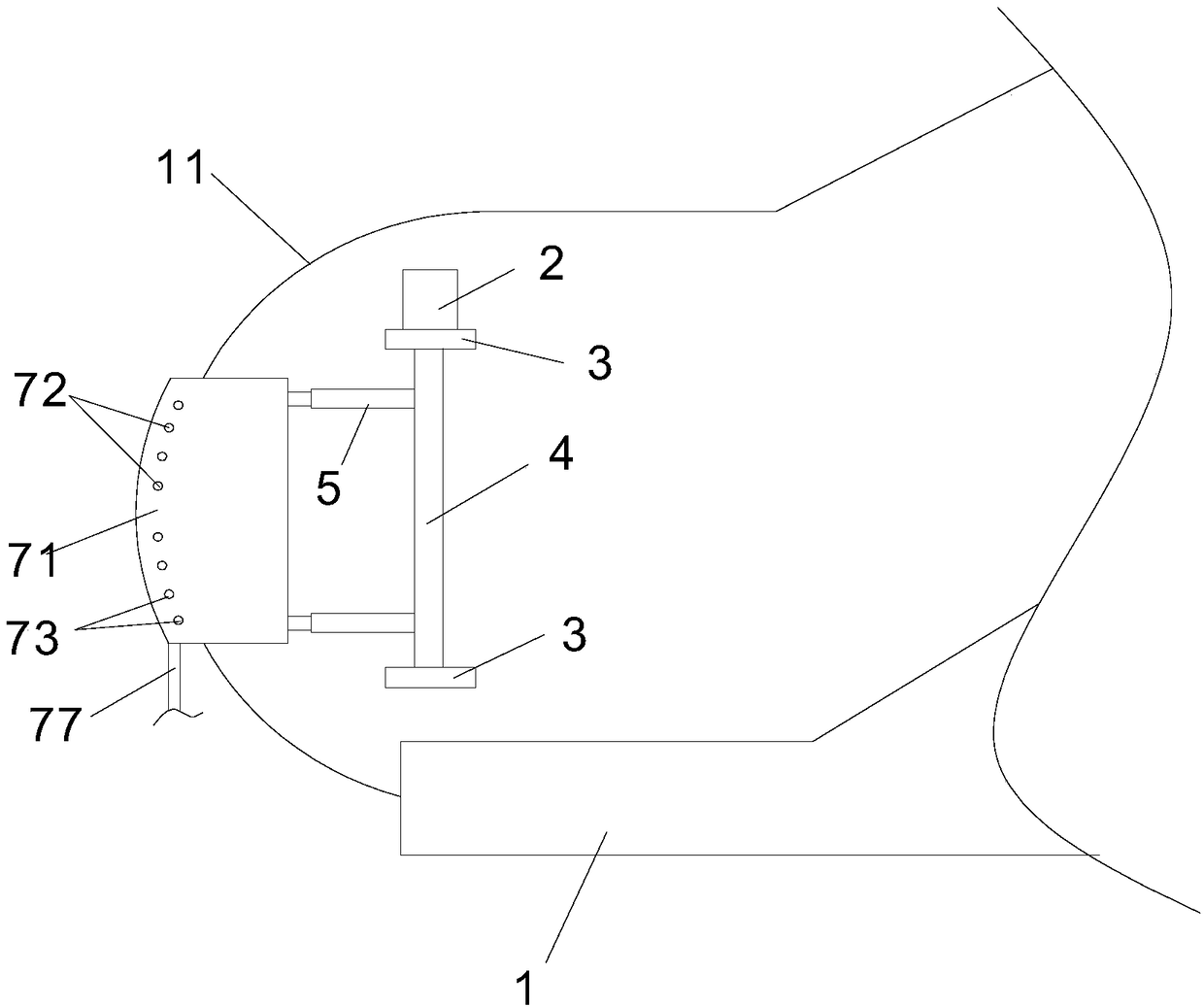
[0024] see Figure 1 to Figure 4 As shown, the first embodiment of the present invention is: the present invention provides a collapsible cleaning device, which is collapsibly arranged on the side of the escalator 1, and the device includes a motor 2, two bearings 3, And the rotating shaft 4, the two bearings 3 are fixed on the side of the escalator 1, the rotating shaft 4 is arranged between the two bearings 3, and the top of the rotating shaft 4 is connected with the rotating shaft of the motor 2, the motor 2. Drive the rotating shaft 4 to rotate forward or reversely, wherein the control of the motor 2 can be controlled by a control switch, that is, a control switch is set on the escalator, and the motor is connected to the control switch; the control switch can control on and off, The motor rotates forward or the motor reverses; the structure and control principle ...
PUM
 Abstract
Description
Claims
Application Information
 - Generate Ideas
- Intellectual Property
- Life Sciences
- Materials
- Tech Scout
- Unparalleled Data Quality
- Higher Quality Content
- 60% Fewer Hallucinations
Browse by: Latest US Patents, China's latest patents, Technical Efficacy Thesaurus, Application Domain, Technology Topic, Popular Technical Reports.
© 2025 PatSnap. All rights reserved.Legal|Privacy policy|Modern Slavery Act Transparency Statement|Sitemap|About US| Contact US: help@patsnap.com