
Novel biocatalysis technology and catalyst equipment

A technology of biocatalysis and catalyst, applied in chemical/physical/physicochemical processes, chemical/physical/physicochemical fixed reactors, chemical instruments and methods, etc., can solve the problems of operator injury and safety hazards of catalytic equipment, etc. Achieve the effect of increasing the fusion rate and shortening the fusion time

Inactive Publication Date: 2018-06-26
郭林惠
View PDF0 Cites 0 Cited by
  • Summary
  • Abstract
  • Description
  • Claims
  • Application Information

AI Technical Summary

Problems solved by technology

[0002] Catalysts are often used in biological experiments to accelerate the reaction of biological solutions. In order to speed up the rapid fusion of catalysts and biological solutions, high-speed rotation and fusion methods are often used in existing systems. However, existing catalytic equipment often operates at high speeds. , and once the operation is wrong, it will cause great harm to the operator. Therefore, the existing catalytic equipment has a great potential safety hazard

Method used


Image

  • Novel biocatalysis technology and catalyst equipment
  • Novel biocatalysis technology and catalyst equipment
  • Novel biocatalysis technology and catalyst equipment

Examples


Embodiment Construction

[0017] All features disclosed in this specification, or steps in all methods or processes disclosed, may be combined in any manner, except for mutually exclusive features and / or steps.

[0018] Any feature disclosed in this specification (including any appended claims, abstract and drawings), unless expressly stated otherwise, may be replaced by alternative features which are equivalent or serve a similar purpose. That is, unless expressly stated otherwise, each feature is one example only of a series of equivalent or similar features.

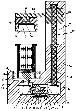
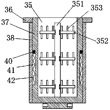
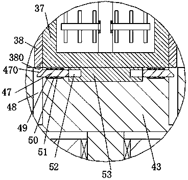
[0019] Such as Figure 1 to Figure 3As shown, a new type of biocatalysis technology and catalyst equipment of the device of the present invention includes a base 10, a frame 26 fixedly installed on the right side of the upper end surface of the base 10 and extended upwards, and the base 10 is provided with The first rotating chamber 11 and the second rotating chamber 23, the first sliding groove 22 connected between the first rotating chamber...


PUM


Abstract

The invention discloses a novel biocatalysis technology and catalyst equipment. The catalyst equipment comprises a base and a rack which is fixedly arranged at the right side of the upper end face ofthe base and upwards extends; a first rotational cavity and a second rotational cavity are formed in the base; a first sliding chute communicate with the first rotating cavity and the second rotatingcavity is formed between the first rotating cavity and the second rotating cavity; a third rotating cavity which is provided with an upward port and is positioned above the first rotating cavity is formed in the upper end face of the base; a rotating stand is rotationally arranged in the third rotating cavity by a bearing; a first rotating shaft is fixedly arranged at the middle of the bottom endface of the rotating stand; the lower end of the first rotating shaft downwards penetrates through the bottom wall of the third rotating cavity, to extend into the first rotating cavity and be fixedlyprovided with a first cone wheel; in addition, the first rotating shaft is rotationally matched with the bottom wall of the third rotating cavity; a first sliding block which can slide leftward and rightward is arranged in the first sliding chute; a first driver is fixedly arranged in the first sliding block; a second rotating shaft and a third rotating shaft which penetrate through the first sliding block are in power connection with the left side and the right side of the first driver.

Description

technical field [0001] The invention relates to the technical field of biochemical equipment, in particular to a novel biocatalysis technology and catalyst equipment. Background technique [0002] In biological experiments, catalysts are often used to accelerate the reaction of biological solutions. In order to speed up the rapid fusion of catalysts and biological solutions, high-speed rotation and fusion methods are often used in existing systems. However, existing catalytic equipment often operates at high speeds. , and once the operation is wrong, it will cause great harm to the operator. Therefore, there is a great potential safety hazard in the existing catalytic equipment. Contents of the invention [0003] Aiming at the deficiencies of the above technologies, the present invention proposes a novel biocatalysis technology and catalyst equipment. [0004] A new type of biocatalysis technology and catalyst equipment of the device of the present invention, comprising...

Claims


Application Information

Patent Timeline
IPC IPC(8): B01J19/18B01J19/00B01F13/04B01F15/00B01F7/18B01F35/60
CPCB01J19/002B01J19/0066B01J19/18B01J2219/00245B01J2219/185B01F27/074B01F27/191B01F27/808B01F35/605B01F27/90B01F35/43B01F2101/2204
Inventor 郭林惠
Owner 郭林惠
Learn More