Improved cooling device for machining center

A processing center and cooling device technology, applied to metal processing equipment, metal processing machinery parts, manufacturing tools, etc., can solve the problems of difficulty in dismantling and maintenance of cooling devices, the need for cooling devices that do not have the need to adjust the position, difficulties, etc., to improve transportation The effect of simplicity, quick installation and convenient transportation

Inactive Publication Date: 2018-06-26
梅金琪
View PDF1 Cites 0 Cited by
  • Summary
  • Abstract
  • Description
  • Claims
  • Application Information

AI Technical Summary

Problems solved by technology

[0002] The cooling device is widely used in the field of machining centers because of its obvious cooling characteristics. The existing cooling device installs the cooling head directly from the side of the processing tool, and releases the coolant at the same time during processing, so that the cooling of the parts during processing is not good. At the same time, it is very difficult to disassemble and repair the cooling device after damage, and the existing cooling device does not have the ability to adjust the position to meet the cooling needs of different angles. It is very difficult to achieve cooling in the entire circumference. When complex parts are used, it can reduce the thermal wear of the tool and reduce the accumulated chipping

Method used


Image

  • Improved cooling device for machining center
  • Improved cooling device for machining center
  • Improved cooling device for machining center

Examples


Embodiment Construction

[0023] All features disclosed in this specification, or steps in all methods or processes disclosed, may be combined in any manner, except for mutually exclusive features and / or steps.

[0024] Any feature disclosed in this specification (including any appended claims, abstract and drawings), unless expressly stated otherwise, may be replaced by alternative features which are equivalent or serve a similar purpose. That is, unless expressly stated otherwise, each feature is one example only of a series of equivalent or similar features.

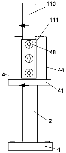
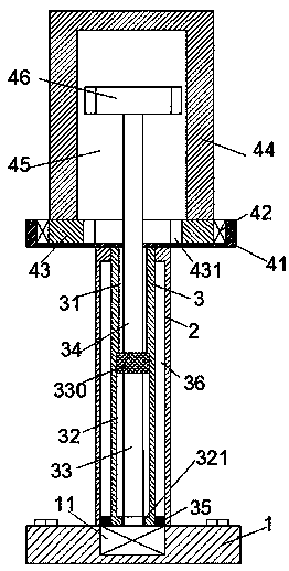
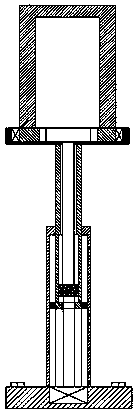
[0025] Such as Figure 1 to Figure 5 As shown, an improved version of the device of the present invention is used for the cooling device of the machining center, including a mounting base 1, a vertical rod 2 fixedly arranged on the top of the mounting base 1, and a swing mechanism 4 arranged above the vertical rod 2, The vertical bar 2 is provided with a communication groove with a notch facing upwards, and a vertical strut 3 that can slide u...


PUM


Abstract

The invention discloses an improved cooling device for a machining center. The improved cooling device for the machining center comprises an installation base, a vertical rod and a rotation mechanism.The vertical rod is fixedly arranged on the top of the installation base. The rotation mechanism is arranged above the vertical rod. A through movement groove with an upward cut is formed in the vertical rod. A vertical supporting rod which can carry out vertical sliding connection is installed in the through movement groove. A supporting rod bottom groove and a slot are formed in the vertical supporting rod, the cut of the supporting rod bottom groove is upward, and the slot is located below the supporting rod bottom groove. A first rotary column is arranged in the slot. A spiral block usedin cooperation with the slot in a spiral manner is arranged on the top of the first rotary column. A second rotary column is arranged in the supporting rod bottom groove in an upward stretch manner. Arotary shell is arranged on the top of the second rotary column. A spray structure is further installed on the shell. The spray structure penetrates through a fixing metal piece and is in butt jointfit with a rotary liquid inlet pipe. A sealing pressure part, a pressure withstand rotary platform, a liquid sealing ring and a connecting block are arranged on the part, with an outlet, of the liquidinlet pipe. A retainer ring, a limiting rotary platform and a rotary platform fixing part are arranged on the part, with an inlet, of the liquid inlet pipe.

Description

technical field [0001] The invention relates to the field of machining centers, in particular to an improved cooling device for machining centers. Background technique [0002] The cooling device is widely used in the field of machining centers because of its obvious cooling characteristics. The existing cooling device installs the cooling head directly from the side of the processing tool, and releases the coolant at the same time during processing, so that the cooling of the parts during processing is not good. At the same time, it is very difficult to disassemble and repair the cooling device after damage, and the existing cooling device does not have the ability to adjust the position to meet the cooling needs of different angles. It is very difficult to achieve cooling in the entire circumference. When complex parts are used, it can reduce the thermal wear of the tool and reduce the accumulated chipping. Contents of the invention [0003] Aiming at the deficiencies o...

Claims


Application Information

Patent Timeline
Patent Type & Authority Applications(China)
IPC IPC(8): B23Q11/10
CPCB23Q11/1076
Inventor 梅金琪
Owner 梅金琪
Why Eureka
Try Eureka