Crane span structure with multiple slots

A bridge and wire trough technology, applied in the field of fire bridges, can solve problems such as confusion and great harm, and achieve the effect of easy management, easy discharge, and possibility of reducing risks

Inactive Publication Date: 2018-06-29
TIANJIN HUIHE ELECTRICAL EQUIP
View PDF0 Cites 6 Cited by
  • Summary
  • Abstract
  • Description
  • Claims
  • Application Information

AI Technical Summary

Problems solved by technology

[0003] When the fire-proof bridge in the prior art is used, it is generally hung on the top of the building. Since there are many internal cables, placing multiple cables inside the bridge is prone to confusion, especially when the cables are damaged. Cables affect each other, causing great harm

Method used


Image

  • Crane span structure with multiple slots
  • Crane span structure with multiple slots
  • Crane span structure with multiple slots

Examples


Embodiment 1

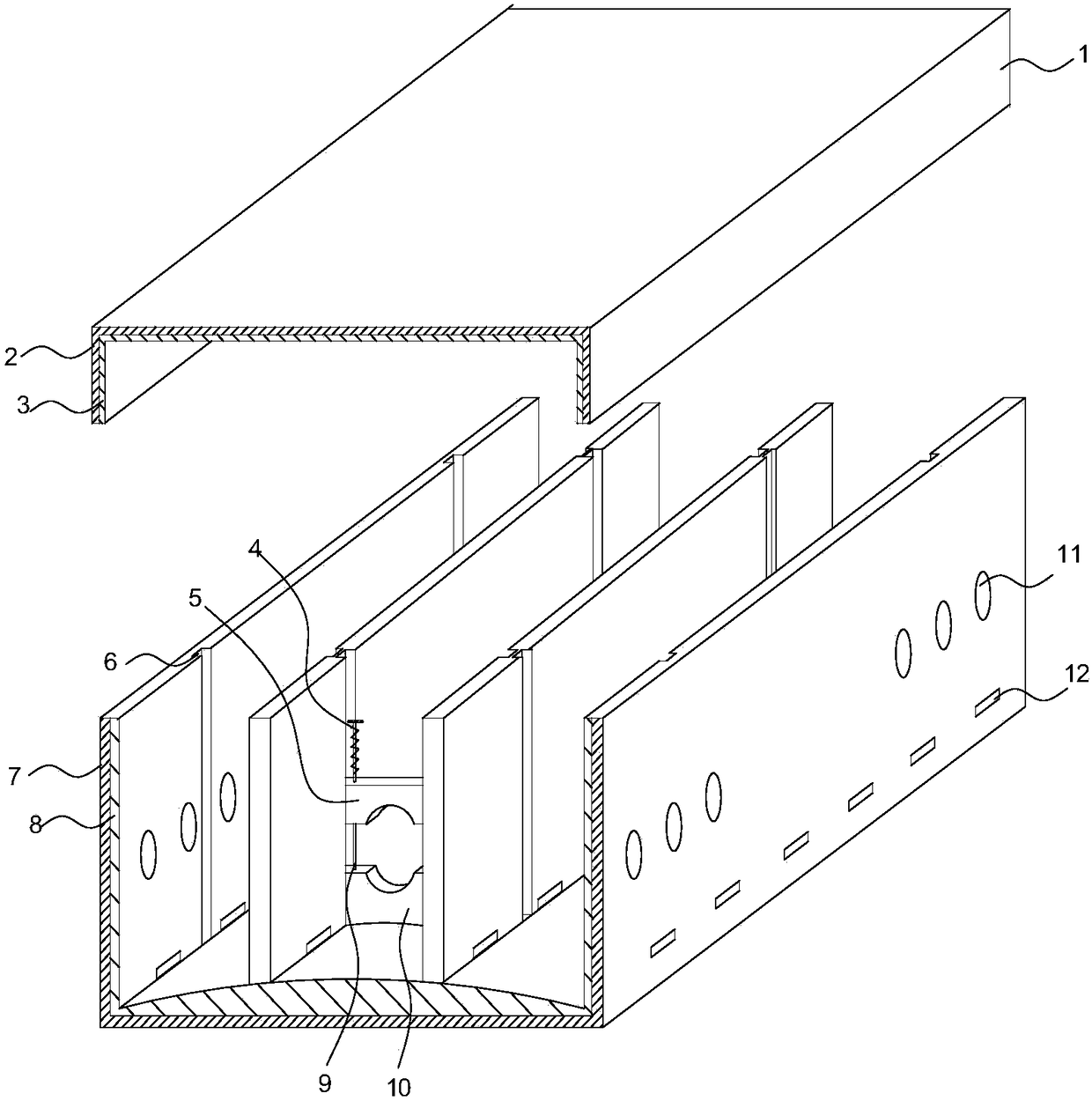
[0018] like figure 1 As shown, the present invention provides a fireproof bridge with multi-wire slots, including a cover and a slot, the cover and the slot are used in conjunction, and the cover is closed on the slot, and the wall of the cover and the slot The walls of the body all include an outer metal layer and an inner fire-proof and heat-insulating layer. The inside of the tank is divided into three sub-slots by fire-proof and heat-insulated panels arranged parallel to the side walls. There are sliding grooves corresponding to the positions, the lower end of the sliding groove is fixed or non-fixedly provided with a lower support block, and an upper pressing block used in conjunction with it is arranged above it, and the two ends of the upper pressing block are respectively slidingly connected with the sliding groove, The upper pressing block and the lower supporting block are respectively provided with symmetrically arranged arc-shaped grooves, and the cables pass throu...

Embodiment 2

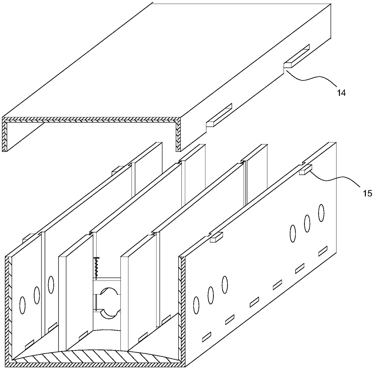
[0025] like Figure 3-Figure 4 As shown, an improvement is made on the basis of Embodiment 1, and a connection structure between the cover and the tank is provided. The two sides of the cover are provided with card slots, and the slots at the corresponding positions are all A clamping block is provided, the clamping block is a square block, the clamping groove is an L-shaped groove, the width of the clamping block is consistent with the width of the longitudinal groove of the L-shaped groove, and the height of the clamping block is the same as that of the L-shaped groove. The height of the transverse grooves is uniform.

[0026] Utilizing the above structure, when the cover body is closed on the tank body, the part of the longitudinal groove of the L-shaped groove corresponds to the block, and moves downward, so that the block enters the L-shaped groove, and after moving in place, When the cover is pushed forward, the locking block is locked in the transverse groove of the L-...


PUM


Abstract

The invention discloses a crane span structure with multiple slots. The crane span structure with multiple slots comprises a cover body and a groove body, wherein the groove body is divided into threesub slots by means of fireproof heat-isolating plates parallel to the side wall; when the crane span structure with multiple slots is used, different types of cables can be separately placed in different sub slots; when faults occur and the cables need to be recognized, the cables can be recognized and operated quickly, and moreover, the probability of risks caused by cable interaction is reduced. In addition, vertical sliding grooves corresponding to positions on two sides are formed in the sub slots and the side wall of the groove body, and lower supporting blocks are fixedly mounted at thelower ends of the slots, and upper pressure blocks matched with the lower supporting blocks in use are arranged above the lower supporting blocks. First, the cables are supported and dangers that thecables are soaked in water condensed in the groove body are avoided; and second, the cables are bundled quickly and conveniently and are conveniently managed, so that the structure is industrially popularized and applied conveniently.

Description

technical field [0001] The invention belongs to the technical field of electromechanical equipment, and in particular relates to a fire-proof bridge with multiple wire slots. Background technique [0002] The fire-proof bridge is mainly composed of fire-proof board composited with glass fiber reinforced material and inorganic adhesive, metal skeleton and other fire-proof base materials. The outer layer is coated with fire-resistant paint, and the fire-proof bridge will not burn when it encounters a fire, thereby blocking the spread of the fire. [0003] When the fireproof bridge in the prior art is used, it is generally hung on the top of the building. Since there are many internal cables, placing multiple cables inside the bridge is prone to confusion, especially when the cables are damaged. Cables affect each other, causing great harm. Contents of the invention [0004] Aiming at the above-mentioned defects in the prior art, the present invention provides a fireproof b...

Claims


Application Information

Patent Timeline
Patent Type & Authority Applications(China)
IPC IPC(8): H02G3/04H02G3/03
CPCH02G3/0406H02G3/03
Inventor 孙巨岗
Owner TIANJIN HUIHE ELECTRICAL EQUIP
Why Eureka
Try Eureka