
Rotating wheel for turbine planetary reducer planet carrier

A technology of gear reducer and rotating wheel, which is applied in the direction of turbine/propulsion lubrication, machine/engine, engine lubrication, etc. It can solve problems such as lubricating oil clogging, large amount of lubricating oil, and risks

Pending Publication Date: 2021-05-18
HISPANO
View PDF1 Cites 0 Cited by
  • Summary
  • Abstract
  • Description
  • Claims
  • Application Information

AI Technical Summary

Problems solved by technology

However, the inside of the rotating wheel will be blocked by the lubricating oil in the annular groove of the rotating wheel, which has a large amount of oil, and may contact the first shaft meshing with the sun gear of the reducer, thereby creating a risk

Method used


Image

  • Rotating wheel for turbine planetary reducer planet carrier
  • Rotating wheel for turbine planetary reducer planet carrier
  • Rotating wheel for turbine planetary reducer planet carrier

Examples


Embodiment Construction

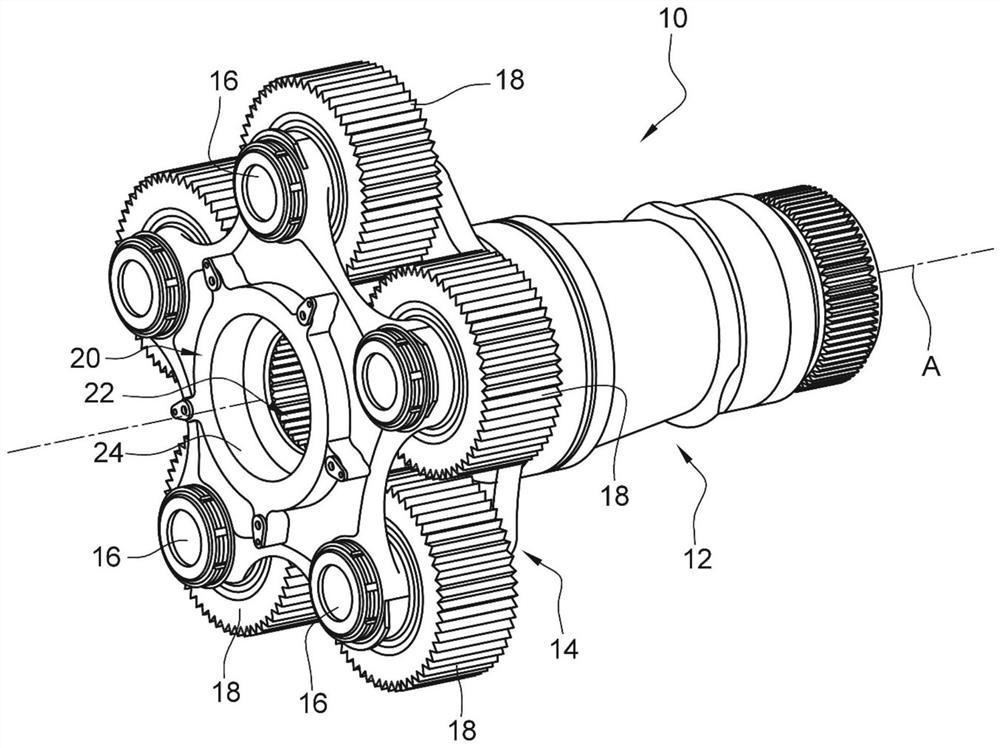
[0040] figure 1 This presents the background to the invention which has been described above.

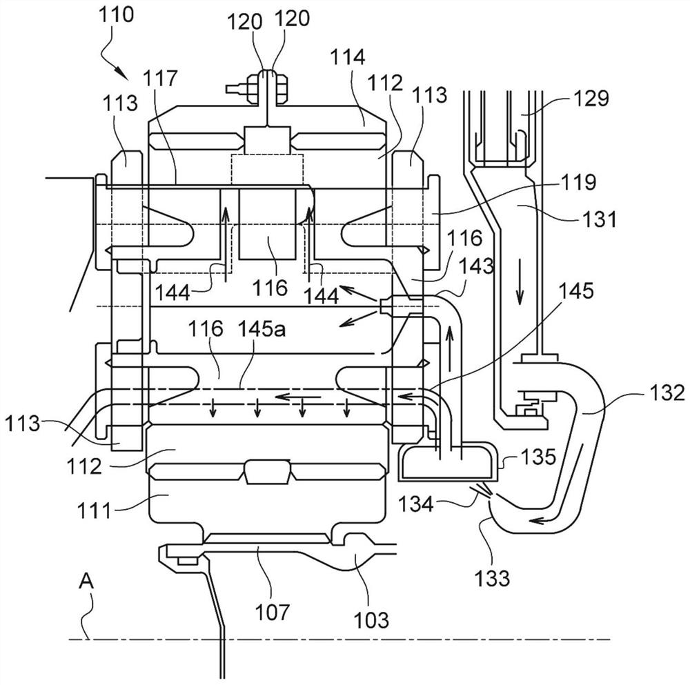
[0041] Figure 2 to Figure 5 The prior art as described in application document FR-A1-3 041 054 is shown.

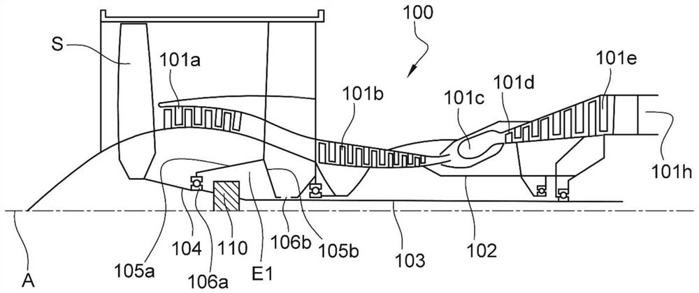
[0042] figure 1 Shown is a turbine 100 generally comprising a fan propeller S, a low pressure compressor 101a, a high pressure compressor 101b, a high pressure turbine 101d, a low pressure turbine 101e and an exhaust nozzle 101h. The high-pressure compressor 101b and the high-pressure turbine 101d are connected by a high-pressure shaft 102, and form a high-pressure body (HP). The low-pressure compressor 101a and the low-pressure turbine 101e are connected by a low-pressure shaft 103, and form a low-pressure body (BP).

[0043] The fan propeller S is driven by a fan shaft 104 , which is coupled to the low pressure shaft 103 via a planetary gear reducer 110 schematically shown here.

[0044] The planetary gear reducer 110 is located in the upstream part of the turbine. In ...


PUM


Abstract

The present invention provides a rotating wheel (230) for a turbine planetary reducer planet carrier. The rotating wheel (230) rotates integrally with the planet carrier and rotates about a longitudinal axis A of the reduction gear, the rotating wheel has an annular shape about the axis and a plurality of lubrication devices (43, 45, 238) including planetary gear bearings of the reduction gear, and the lubricating device comprises an annular cavity (238) located on the inner circumference of the rotating wheel. The rotating wheel for the turbine planetary reducer planet carrier is characterized in that the rotating wheel comprises an inner peripheral wall (246) closed in the radial direction of the annular cavity (238), and further comprises an annular slot (248) extending around the axis and opening in the axial direction and supplying lubricating oil into the annular cavity.

Description

technical field [0001] The invention relates to a rotating wheel for a planetary carrier of a turbine planetary gear reducer. Background technique [0002] The prior art in this field mainly includes the following documents: FR-A1-3 036 763, FR-A1-3 047 279, FR-A1-3 041 054, FR-A1-3 065 773, WO-A1-2015 / 008000 , US-A1-2019 / 301466, US2013313053A1, US-A1-2018 / 306293, US-A1-2019 / 032514, WO-A1-2018 / 189457, US-B2-8,911,318 and WO-A1-2018 / 185186. [0003] A planetary gear reducer for an aircraft turbine typically includes a sun gear connected to a first shaft and a crown gear extending around the sun axis. The planetary gears are located between the sun gear and the crown gear, and meshed with them, and are carried by the planetary carrier connected to the second shaft. [0004] figure 1 A planet carrier 10 as described in application document FR-A1-3 036 763 is shown. The planet carrier 10 comprises a cylinder 12 connected to a second shaft, the longitudinal ends of which are ...

Claims


Application Information

Patent Timeline
Patent Type & Authority Applications(China)
IPC IPC(8): F16H57/04F01D25/18
CPCF16H57/043F16H57/0456F16H57/0479F16H57/0482F01D25/18F16H57/0427F02C7/06F01D15/12F05D2260/40311F05D2260/98F02C7/36Y02T50/60F05D2220/323F16H2057/085
Inventor 马修·让·查理尔安托万·雅克·玛丽·彭纳西诺让-查尔斯·米歇尔·皮埃尔·迪乔凡尼弗洛里安·拉普帕波特
Owner HISPANO
Learn More