Novel energy charging pile device

A charging pile and new energy technology, applied in circuit devices, battery circuit devices, charging stations, etc., can solve the problems of unadjustable charging orientation, lack of energy saving, and increased power consumption, etc., to achieve angle adjustment and storage work, Simple structure and the effect of prolonging the service life

Inactive Publication Date: 2018-06-29
广州创码信息科技有限公司
View PDF4 Cites 1 Cited by
  • Summary
  • Abstract
  • Description
  • Claims
  • Application Information

AI Technical Summary

Problems solved by technology

[0002] The new energy charging pile is an important supporting facility for new energy vehicles and an important charging carrier for providing electric energy for new energy vehicles. However, the traditional charging piles are mostly connected to the main

Method used


Image

  • Novel energy charging pile device
  • Novel energy charging pile device
  • Novel energy charging pile device

Examples


Embodiment Construction

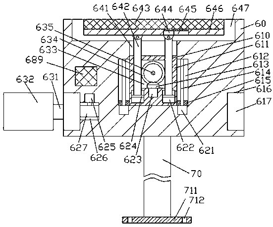
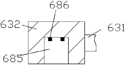
[0014] Such as Figure 1-Figure 3 As shown, a new energy charging pile device of the present invention includes an assembly frame 60 and a charging base 632 cooperatingly installed on the assembly frame 60, the charging base 632 is provided with a slot 685, and the slot 685 The inner top wall is provided with a power supply pin 686, and the top end surface of the assembly frame 60 is provided with an installation cavity 647, and the inner wall of the assembly frame 60 on the lower side of the installation cavity 647 is connected with a first sliding connection cavity 641. The first sliding joint cavity 641 is slidingly fitted with a sliding joint seat 611, the left and right sides of the sliding joint seat 611 are provided with push-up structures, and the inner wall of the sliding joint seat 611 is provided with a first transition cavity 633, The first adapter shaft 635 is extended front and rear in the first adapter chamber 633 and is connected to the front and rear inner wal...


PUM


Abstract

The invention discloses a novel energy charging pile device. The novel energy charging pile device comprises an assembly frame and a charging base which is arranged on the assembly frame in a matchingway; a slot is formed in the charging base; the inner top wall of the slot is provided with power charging pins; a mounting-connecting cavity is formed in the top end face of the assembly frame; a first slide-connecting cavity which is communicated with the inner wall body of the assembly frame is formed on the lower side of the mounting-connecting cavity; a slide-connecting base which is in slide-connection fit with the first side-connecting cavity; the left side and right side of the slide-connecting cavity are provided with pushing structures; a first switching cavity is formed on the inner wall body of the slide-connecting base; a first switching shaft which can extend forwards and backwards, and is in rotation fit connection with the front wall and back wall of the first switching cavity is arranged in the first switching cavity; a first conical wheel is fixedly arranged on the outer surface of the first switching shaft along the circumferential direction; the inner bottom wall of the first switching cavity is provided with a second conical wheel which is in fit connection with the first conical wheel; the bottom end face of the second conical wheel is in dynamical fit connection with a first power-driven rotator.

Description

technical field [0001] The invention relates to the technical field of new energy charging piles, in particular to a new energy charging pile device. Background technique [0002] The new energy charging pile is an important supporting facility for new energy vehicles and an important charging carrier for providing electric energy for new energy vehicles. However, the traditional charging piles are mostly connected to the mains, which greatly increases the consumption of electric energy and does not have the ability to save energy. At the same time, the setting mode of the existing charging pile is simple, and its charging position cannot be adjusted, so there are major defects. Contents of the invention [0003] The technical problem to be solved by the present invention is to provide a new energy charging pile device, which can solve the above-mentioned problems in the prior art. [0004] The present invention is achieved through the following technical solutions: A new...

Claims


Application Information

Patent Timeline
IPC IPC(8): H02J7/00H02J7/35B60L11/18
CPCB60L53/31H02J7/0045H02J7/35Y02T10/70Y02T10/7072Y02T90/12
Inventor 袁承宇
Owner 广州创码信息科技有限公司
Why Eureka
Try Eureka