Linear encoding measurement device, and linear encoding spatial position measurement method and system

A technology of spatial position and measuring device, applied in the field of measurement, can solve the problems of inconvenient storage and use, and high requirements on the frame accuracy of measuring equipment, and achieve the effects of convenient storage, accurate measurement, and low accuracy requirements.

Active Publication Date: 2018-07-06
BYD CO LTD
View PDF7 Cites 6 Cited by
  • Summary
  • Abstract
  • Description
  • Claims
  • Application Information

AI Technical Summary

Problems solved by technology

[0003] The purpose of the present invention is to provide a method for measuring the spatial position of the cable code, aiming at solving the problem that the existing cable coded space measurement method has high requirements for the frame accuracy of the measuring equipment and is inconvenient to store and use

Method used


Image

  • Linear encoding measurement device, and linear encoding spatial position measurement method and system
  • Linear encoding measurement device, and linear encoding spatial position measurement method and system
  • Linear encoding measurement device, and linear encoding spatial position measurement method and system

Examples


Embodiment 1

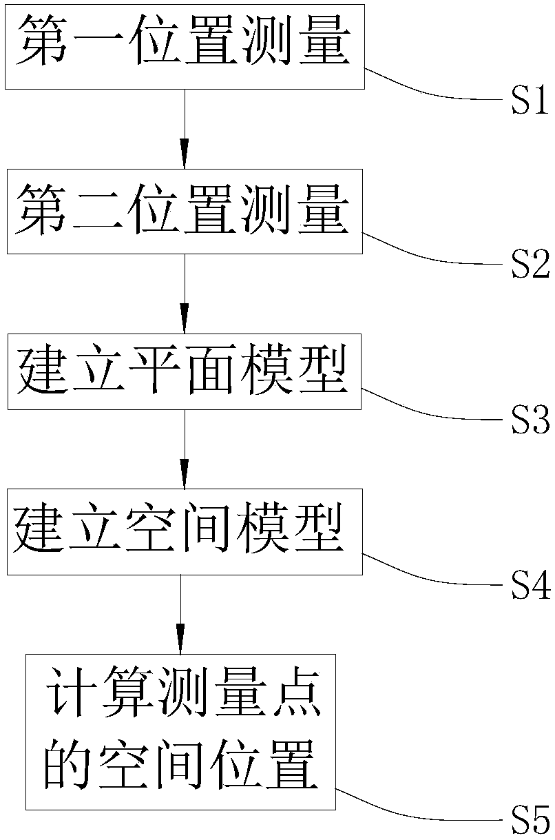
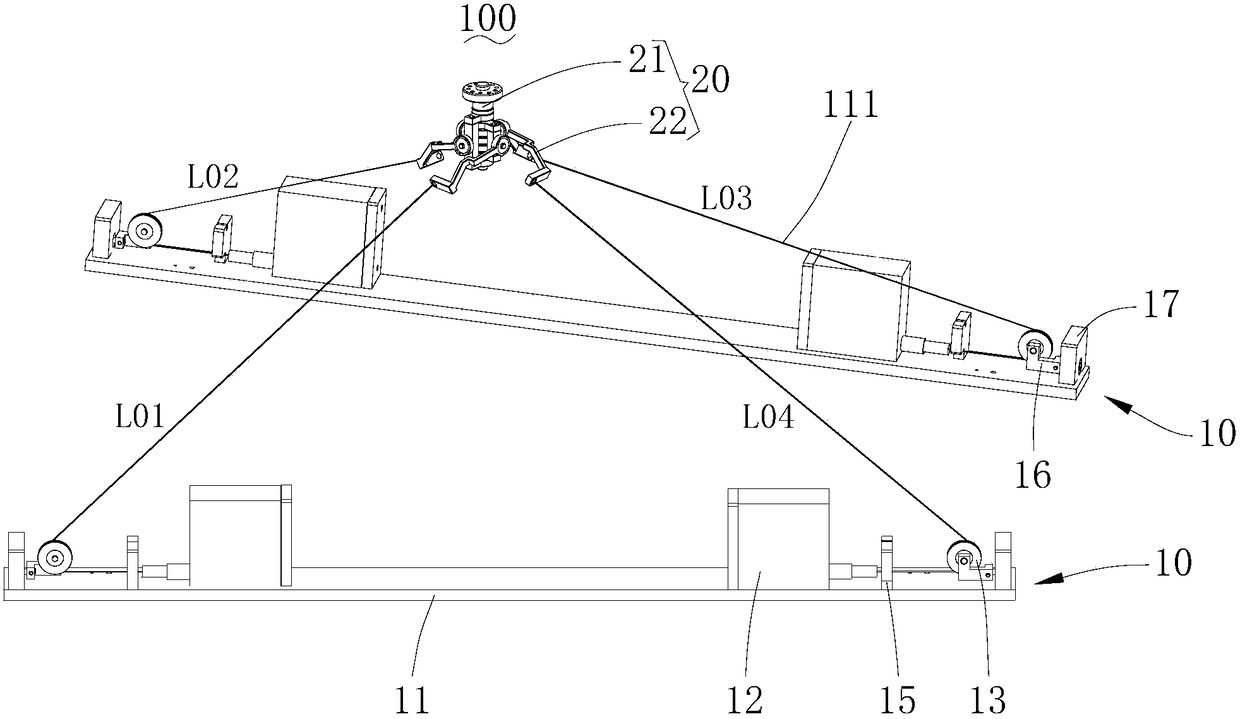
[0023] see Figure 2 to Figure 6 , the first embodiment of the present invention provides a method for measuring the spatial position of the wire coding, the method uses the wire coding measuring device 100 for measurement.

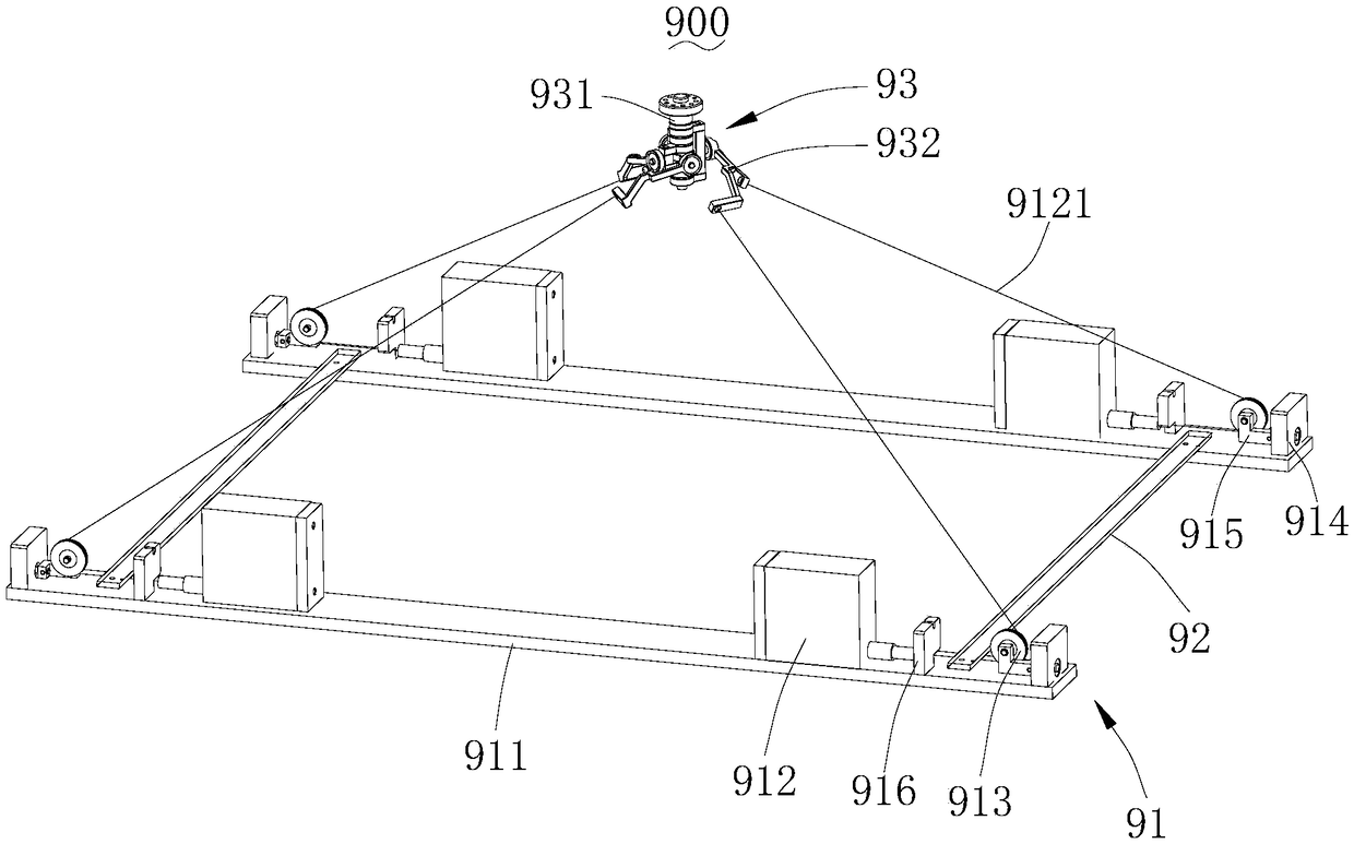
[0024] In this embodiment, the wire-drawing code measurement device 100 includes a centripetal mechanism 20 and two measurement frames 10 . The centripetal mechanism 20 includes a connecting head 21 and four centripetal legs 22 mounted on the connecting head 21 . Each of the measuring frames 10 includes a base 11, and the base 11 is symmetrically installed with: two pull-wire encoders 12, two deflection pulleys 13 respectively guiding the stay wires 111 of each of the stay-wire encoders 12, respectively The support frame 16 supporting the two deflection pulleys 13, the support 17 pivotally connected to each of the support frames 16 and the positioning block 15 respectively positioning the initial positions of the pull wires 111 of each of the pull wire e...

Embodiment 2

[0093] see Figure 7 and Figure 8 , a method for measuring the spatial position of a cable code provided in Embodiment 2 of the present invention. This method is measured using a wire-drawn code measuring device 100b. The pull-wire code measuring device 100b includes a centripetal mechanism 20b and a measuring frame 10b, and the centripetal mechanism 20b includes a connecting head 21b and two centripetal legs 22b installed on the connecting head 21b. Each measuring frame 10b includes a base 11b, and the base 11b is symmetrically installed with: two pull-wire encoders 12b, two deflection pulleys 13b respectively guiding the stay wires 111b of each pull-wire encoder 12b, supporting two deflection pulleys 13b respectively The support frame 16b, the support 17b pivotally connected with each support frame 16b and the positioning block 15b respectively positioning the initial position of the pull wire 111b of each pull wire encoder 12b, the lower tangent point of each pull wire 1...


PUM


Abstract

The present invention is suitable for the technical field of measurement, and provides a linear encoding spatial position measurement method. The method comprises the following steps of: measurement of a first position: locating a centripetal mechanism at a measured point, and performing measurement at the first position by employing at least one measurement frame; measurement of a second position: performing measurement at the second position by employing the at least one measurement frame; establishment of a planar model; establishment of a space model; and calculation of the spatial position of the measured point. The centripetal mechanism is located at the measured point, the at least one measurement frame is employed to perform measurement of the two positions, the planar model and the stereoscopic space model of the centripetal mechanism and the at least one measurement frame at two positions are established, the spatial position of the measured point is calculated through mathematical transformation, and therefore, the usage is convenient, it is not needed that the at least one measurement frame at the two positions are parallel, the precision demand of the measurement device is low to facilitate storage of the measurement device, and the spatial position of the measured point can be accurately measured.

Description

technical field [0001] The invention belongs to the technical field of measurement, and in particular relates to a wire code measuring device, a wire code spatial position measurement method using the wire code measurement device, and a measurement system using the wire code spatial position measurement method. Background technique [0002] Currently, there are two common ways to measure spatial coordinates. One is to measure with a three-coordinate measuring instrument; the other is to use a laser tracker. However, the three-coordinate measuring instrument is bulky, expensive, and usually measures in a fixed position. If it needs to be moved, the system must be recalibrated; the dynamic measurement speed of the laser tracker is limited, and the price is very expensive. In addition to the above two commonly used measurement methods, there is also a relatively cheap measurement mechanism, that is, spatial position measurement based on wire-drawn encoders. This method of spat...

Claims


Application Information

Patent Timeline
IPC IPC(8): G01D5/04G01B5/00
CPCG01B5/00G01D5/04
Inventor 蒋琼艳周虎汤海舰欧阳德运谢卫陈慧玲
Owner BYD CO LTD
Why Eureka
Try Eureka