Supercharge Your Innovation With Domain-Expert AI Agents!

Wiring duct available for convenient penetration and insertion of wire ties

一种扎线带、线槽的技术,应用在便于穿插扎线带的线槽领域,能够解决增加劳动量、降低劳动效率、费时费力等问题,达到提高穿插效率、提高劳动效率的效果

Active Publication Date: 2018-07-06
GUANGDONG HONGJI LINE PIPE IND
View PDF4 Cites 0 Cited by
  • Summary
  • Abstract
  • Description
  • Claims
  • Application Information

AI Technical Summary

Problems solved by technology

[0003] In the wiring troughs of current power cabinets and large-scale electrical equipment, most of them are simply "concave"-shaped wiring troughs fixed on the body, and some cable tie holes are evenly arranged on the wiring troughs to facilitate the installation of cable ties. When the wires are filled in the wire slot, the wires will be fixed in the wire slot with a cable tie, but in the process of binding the wires with the cable tie, because the wires are covered in the wire slot, it will be very difficult to pass through the cable tie hole. Laborious, so threading wires will be time-consuming and labor-intensive
Another way to tie the cable ties is to first fill the wire trough with cable ties, and then spread the wires on the cable ties. When the wires are full, you can tie the cable ties to the wires. Fixed, but in these two ways, the cable tie is in direct contact with the wires. When the wires are bundled and tightened, the cable tie is in close contact with the wires, and the wires are directly in contact with the trunking body, so that the wires are damaged to a certain extent, thus leaving However, if it is necessary to protect the wires, it is necessary to cover the wire groove with a rubber layer, which further increases the labor load and reduces the labor efficiency.

Method used


Image

  • Wiring duct available for convenient penetration and insertion of wire ties
  • Wiring duct available for convenient penetration and insertion of wire ties
  • Wiring duct available for convenient penetration and insertion of wire ties

Examples


Embodiment Construction

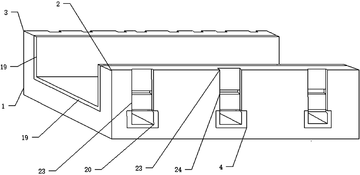
[0037] Such as figure 1 with figure 2 As shown, a wire groove that is convenient for inserting cable ties includes a wire groove body 1 and a groove body 2 and b groove body 3 provided on both sides of the wire groove body 1, and the inner wall of the wire groove body 1 is provided with There is a layer of rubber protective layer 19, the a groove body 2 covered by the bottom of the rubber protective layer 19 is provided with a plurality of a cable tie sockets 4, and the b groove body 3 is provided with a plurality of a cable tie sockets 4 corresponding Corresponding b cable tie interface 5.

[0038] Such as Image 6 As shown, wherein the a cable tie socket 4 corresponds to three b cable tie interfaces 5 .

[0039]Wherein the bottom of the trunking body 1 is provided with a cable tie guide groove 6 for the cable tie to pass through, and the cable tie guide groove 6 is correspondingly arranged at the a cable tie socket 4 and the three b cable tie interfaces 5, and is in the ...


PUM


Abstract

The invention discloses a wiring duct available for convenient penetration and insertion of wire ties. The wiring duct comprises a wiring duct body, a groove a and a groove b, and two sides of the wiring duct body are provided with the groove a and the groove b respectively. The wiring duct is characterized in that the inner wall of the wiring duct body is provided with a rubber protective layer,the groove a covered by the bottom of the rubber protective layer is provided with a plurality of wire tie sockets a, and the groove b is provided with a plurality of wire tie sockets b correspondingto the wire tie sockets a. A rotating wire tie guide barrel is arranged in each wire tie socket a, the top of each wire tie socket a is provided with a wire tie positioning device, two sides of each wire tie socket a are provided with inner grooves respectively, a cylindrical fixing barrel is arranged in each inner groove, a semicircular convex plate in connection with a spring is arranged in eachfixing barrel, and the wire tie guide barrels are clamped by the semicircular convex plates. The wiring duct is simple in structure and convenient to use and is convenient for the wire ties to penetrate while comprehensive protection of wires in the wiring duct is realized, and accordingly wire fixation is realized.

Description

technical field [0001] The invention relates to the field of a power line trough, in particular to a line trough that is convenient for inserting cable ties. Background technique [0002] With the continuous development of society and the continuous advancement of science and technology, people's living standards are also constantly improving. When living standards are improving, there are more and more large ships and electrical equipment. In the field of power equipment , The wire trough for wiring is an indispensable device in electrical equipment. The wire trough can fix the wires completely and stably, and at the same time avoid the mess caused by too many wires, thereby further ensuring the safety of electrical equipment and in daily life. During the maintenance and inspection process, the occurrence of electric shock accidents caused by messy wires can be further avoided. [0003] In the wiring troughs of current power cabinets and large-scale electrical equipment, m...

Claims


Application Information

Patent Timeline
Patent Type & Authority Applications(China)
IPC IPC(8): H01R13/72
CPCH01R13/72
Inventor 不公告发明人
Owner GUANGDONG HONGJI LINE PIPE IND
Features
  • R&D
  • Intellectual Property
  • Life Sciences
  • Materials
  • Tech Scout
  • Unparalleled Data Quality
  • Higher Quality Content
  • 60% Fewer Hallucinations
Learn More